2 layers112.6 × 85.4 mm

 dilshan/i2c-test-terminal20
I2C hardware test terminal/master mode emulator.
I2c tester is an open-source printed circuit board by dilshan, from the dilshan/i2c-test-terminal repository on GitHub, published under the MIT licence. It is a 2-layer board of 96.9 × 110.7 mm with 69 parts on 46 nets, routed with 703 tracks and 18 vias.
It is built around the ATMEGA16A-PU, LM2596T-5.0 and 2SC945, with the EC2-5NU among its other parts. Its parts include 23 resistors, 11 capacitors, 7 diodes, 7 transistors and 7 connectors. It belongs with the computers and single-board computers boards and the AVR (ATmega, ATtiny) boards of this library.


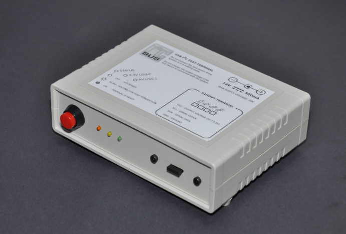
The I2C master mode emulator allows communication with I2C devices by sending or receiving data to/from the I2C bus. To issue the I2C commands, the emulator should connect to a PC over the USB port. After initializing the emulator, the PC and directly control the I2C slave chip/module.
This emulator is based on ATmega16A MCU. The USB communication channel is develop using the V-USB firmware.
To simplify the assembly, the PCB of this emulator is designed on a single-side board. The dimensions of the PCB are 96.77mm × 110.73mm. All the parts used in this project are through-hole-type, generally available components.
This emulator needs an external power supply, and the recommended supply voltage is between 12V - 15V.
The control software of the emulator is developed using libusb and tested only with Linux operating systems. The current firmware and control software support I2C emulation on 100kHz, 250kHz, and 400kHz clock rates.
Initially, we develop this emulator to work with 5V I2C devices, but later it has extended to work with 3.3V I2C devices. The 3.3V design is still under testing, and at the prototyping stage, we found a couple of issues in 3.3V mode.
In 3.3V mode, the required output level is available only if the emulator is in a "ready" state. In all the other states, it provides 5V output. Therefore in 3.3V mode, necessary precautions need to be taken to protect the slave device from over-voltage damages.
This project is an open-source hardware project. All the content of this project are distributed under the terms of the following license:
| Qty | Value | Footprint | References |
|---|---|---|---|
| 6 | 10K | Resistor_THT:R_Axial_DIN0207_L6.3mm_D2.5mm_P10.16mm_Horizontal | R108, R109, R112, R113, R116, R117 |
| 5 | 2SC945 | Package_TO_SOT_THT:TO-92_HandSolder | Q101, Q102, Q103, Q104, Q107 |
| 4 | 5.6K | Resistor_THT:R_Axial_DIN0309_L9.0mm_D3.2mm_P15.24mm_Horizontal | R101, R105, R114, R115 |
| 3 | 0.1MFD | Capacitor_THT:C_Disc_D12.5mm_W5.0mm_P10.00mm | C103, C104, C109 |
| 3 | 1K | Resistor_THT:R_Axial_DIN0309_L9.0mm_D3.2mm_P15.24mm_Horizontal | R103, R110, R118 |
| 3 | 1N4001 | Diode_THT:D_DO-41_SOD81_P10.16mm_Horizontal | D101, D102, D103 |
| 3 | 22K | Resistor_THT:R_Axial_DIN0309_L9.0mm_D3.2mm_P15.24mm_Horizontal | R102, R106, R119 |
| 3 | EC2-5NU | Relay_THT:Relay_DPDT_Kemet_EC2 | K101, K102, K103 |
| 2 | 10MFD | Capacitor_THT:CP_Radial_D5.0mm_P2.00mm | C107, C111 |
| 2 | 27pF | Capacitor_THT:C_Disc_D5.0mm_W2.5mm_P2.50mm | C101, C102 |
| 2 | 2N7000 | Package_TO_SOT_THT:TO-92_HandSolder | Q105, Q106 |
| 2 | 3.3V-LED | Connector_PinHeader_2.54mm:PinHeader_1x02_P2.54mm_Vertical | J102, J103 |
| 2 | 3.6V | Diode_THT:D_DO-35_SOD27_P7.62mm_Horizontal | D105, D106 |
| 2 | 330R | Resistor_THT:R_Axial_DIN0309_L9.0mm_D3.2mm_P15.24mm_Horizontal | R104, R111 |
| 2 | 68R | Resistor_THT:R_Axial_DIN0309_L9.0mm_D3.2mm_P15.24mm_Horizontal | R121, R122 |
| 1 | 0.1MFD | Capacitor_THT:C_Disc_D9.0mm_W5.0mm_P5.00mm | C106 |
| 1 | 0.47MFD | Capacitor_THT:C_Rect_L16.5mm_W7.0mm_P15.00mm_MKT | C110 |
| 1 | 1.5K | Resistor_THT:R_Axial_DIN0309_L9.0mm_D3.2mm_P15.24mm_Horizontal | R123 |
| 1 | 10K | Resistor_THT:R_Axial_DIN0309_L9.0mm_D3.2mm_P15.24mm_Horizontal | R107 |
| 1 | 16.000MHz | Crystal:Crystal_HC49-U_Vertical | Y101 |
| 1 | 1N4004 | Diode_THT:D_DO-41_SOD81_P10.16mm_Horizontal | D107 |
| 1 | 1N5824 | Diode_THT:D_DO-41_SOD81_P10.16mm_Horizontal | D104 |
| 1 | 220MFD | Capacitor_THT:CP_Radial_D6.3mm_P2.50mm | C108 |
| 1 | 33K | Resistor_THT:R_Axial_DIN0309_L9.0mm_D3.2mm_P15.24mm_Horizontal | R120 |
| 1 | 33uH | Inductor_THT:L_Toroid_Vertical_L14.0mm_W5.6mm_P5.30mm_Bourns_5700 | L101 |
| 1 | 470MFD | Capacitor_THT:CP_Radial_D8.0mm_P3.50mm | C105 |
| 1 | 5V-LED | Connector_PinHeader_2.54mm:PinHeader_1x02_P2.54mm_Vertical | J101 |
| 1 | 60R/100MHz | Inductor_THT:L_Axial_L6.6mm_D2.7mm_P10.16mm_Horizontal_Vishay_IM-2 | FB101 |
| 1 | ATmega16A-PU | Package_DIP:DIP-40_W15.24mm_Socket_LongPads | U101 |
| 1 | AVR-ICP | Connector_PinHeader_2.54mm:PinHeader_2x05_P2.54mm_Vertical | J104 |
| 1 | DC-IN | Connector_Phoenix_MC_HighVoltage:PhoenixContact_MCV_1,5_2-G-5.08_1x02_P5.08mm_Vertical | J106 |
| 1 | I2C-OUT | Connector_PinHeader_2.54mm:PinHeader_1x04_P2.54mm_Vertical | J107 |
| 1 | LD33V | Package_TO_SOT_THT:TO-220-3_Vertical | U103 |
| 1 | LM2596T-5 | Package_TO_SOT_THT:TO-220-5_P3.4x3.7mm_StaggerOdd_Lead3.8mm_Vertical | U102 |
| 1 | USB_B | Connector_USB:USB_B_Lumberg_2411_02_Horizontal | J105 |
| 1 | XF040 | Fuse:Fuse_Bourns_MF-RG300 | F101 |
The 65 most common of 69 parts.


sverrham/diy-smu
DIY Source Measurement Unit, four quadrant powersupply and ?.? digit volt/current meter.

Acliad/toast-o-meter
Breadboard mounted DMM with volts, amps, ohms, continuity, and diode feature.


It measures 96.9 × 110.7 mm and has 2 copper layers, 1.6 mm thick.
69 parts, built around the ATMEGA16A-PU, LM2596T-5.0, 2SC945 and EC2-5NU. The full list of its parts is on this page, with links to each part's symbol and footprint where PCBKit's library has them.
From the dilshan/i2c-test-terminal repository on GitHub, at the commit this page was made from: the board is design/i2c-tester.kicad_pcb. PCBKit opens the board in the browser, with nothing to install.
Its repository publishes it under the MIT licence: you may reuse it on that licence's terms (keep the author's notice, and for a copyleft licence share your changes alike).