2 layers

 diegodierick/Heater-shield1
This repository contains code and design files for a four channel Arduino based heater.
PIDheaterUnoShield is an open-source printed circuit board by diegodierick, from the diegodierick/Heater-shield repository on GitHub. It is a 2-layer board of 68.6 × 53.3 mm with 40 parts on 61 nets, routed with 585 tracks and 148 vias.
It is built around the CD4050BD, R-78E5.0-0.5 and PCF8523T, with the CR1220-2 among its other parts. Its parts include 9 resistors, 5 capacitors, 5 connectors, 4 ICs and 4 transistors.


This repository contains code and design documentation for an Arduino based four channel heater controller. The system monitors ambient temperature and temperatures in up to four targets. The power to four heaters associated to the targets is continuously adjusted to raise the target temperature above ambient by a configurable offset. Measured temperatures and power input to each heater can be logged to an SD card. Although originally developed for heating small microcosms in biological and ecological research, it is a flexible system with potential applications in various fields.
This repository is part of a publication which you can find here http://dx.doi.org/10.1111/2041-210X.13391.
The code is organized in a main tab HeaterShield.ino and a number of tabs grouping related code. Keep all files together in a folder named HeaterShield in order for things to work. You will need to have the Arduino IDE installed to easily compile and upload code to the board. You will also need to have the OneWire, New LiquidCrystal, Sdfat and the Adafruit RTClib libraries installed in order for the code to compile. This code was created and tested using Arduino IDE 1.6.2.
The heart of the system consists of an Arduino UNO microcontroller board or compatible clone with a custom heater controller shield stacked on top. The system is powered through the shield from a DC power supply. In many cases switched mode power supplies (SMPS) will be a good fit. The shield allows to connect five DS18B20 temperature sensors (one reference and four heated units) and four heaters which are powered from the unmodified DC supply voltage. The shield has a real-time clock (RTC) and micro-SD slot on board to facilitate data logging. Below an overview of the complete system.
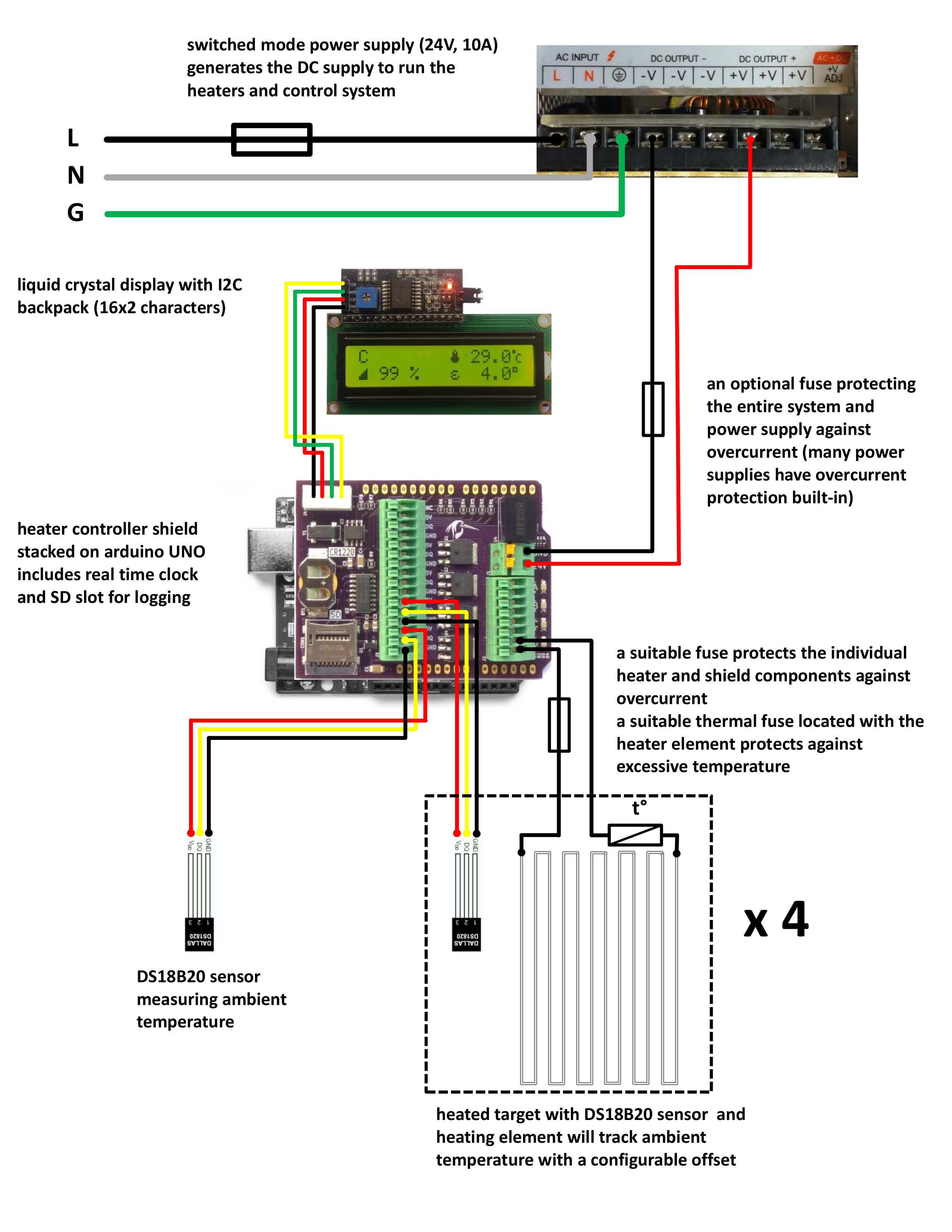 .
The main function of the heater controller shield, besides serving as wiring hub, is to switch power to the heaters using mosfets (electronic switching component). The mosfets are independently controlled by pulse width modulation capable pins of the microcontroller (Arduino pins 3, 5, 6 and 9) which allows gradual control of heater power. Below an overview of the main parts of the heater shield.
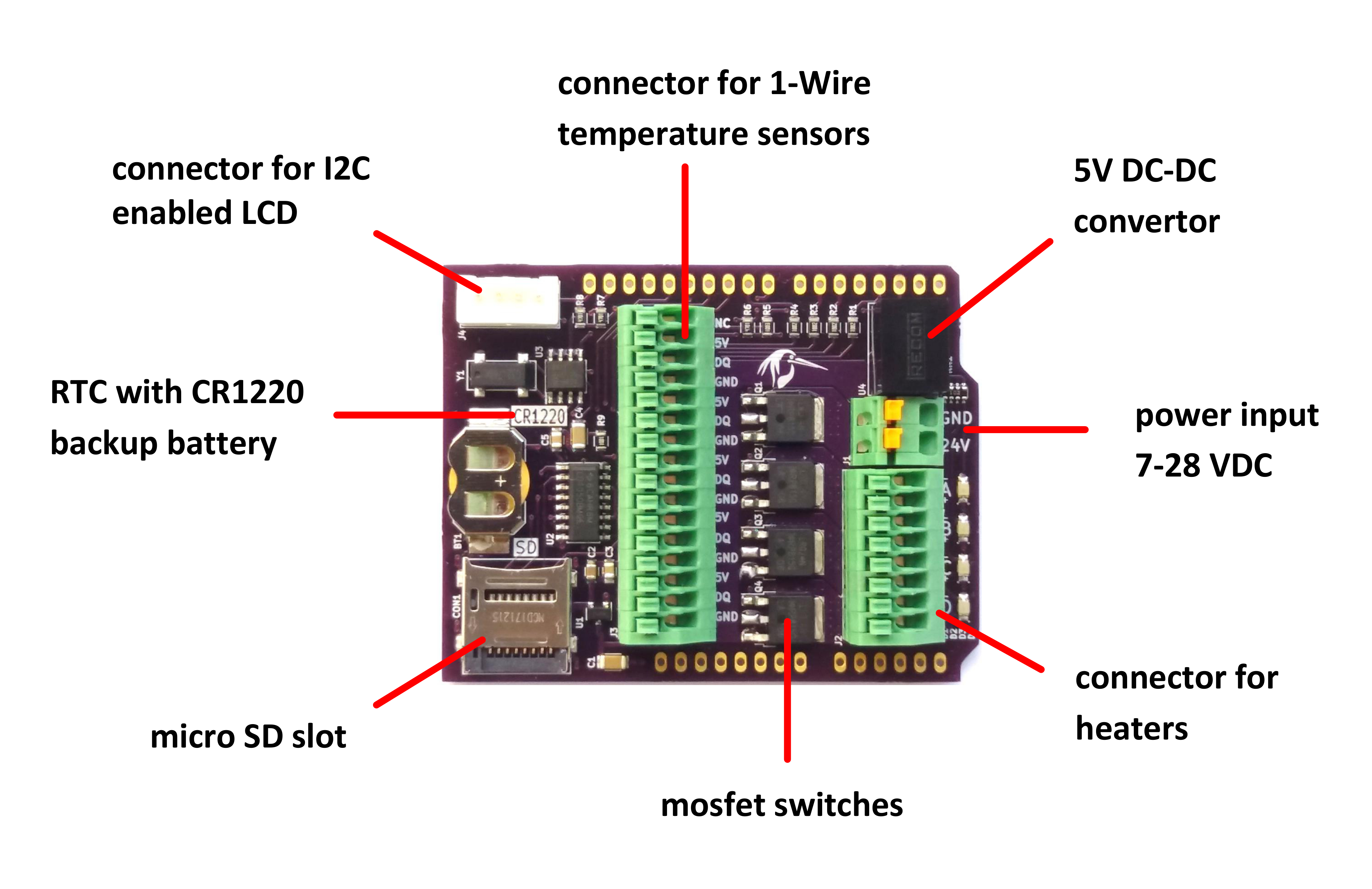 .
The shield is custom built for this application. The KiCad design files can be found in the folder DesignDocs\KiCad. Gerber files for the two-layer board and front paste stencil were generated from within KiCad following the instructions provided by SeedStudio. These gerber files were never used to fabricate boards (I upload KiCad files directly), so please double-check the files before sending them out and let me know if any issues arise. The ZIP archives for board files and stencil can be found in the Gerber folder located in the DesignDocs. The bill of materials HeaterShieldBOM.csv in the DesignDocs was exported from the Digi-Key BOM manager and includes pricing (as of July 2019). Components for a single board purchased through Digi-Key will cost around $20. The Phoenix connectors are modular and the 16 pin connector J3 is actually put together from two 8 pin connectors, so you will not find the 16 pin version in the BOM.
The shield has an input connector to supply 7-28 volts DC to the system. This supply voltage is routed via mosfets to a connector where the heater elements attach. Make sure the DC power supply can provide the maximum current expected for a specific heater configuration. We used the system with a 24V 10A switched mode power supply (SMPS) which is suitable for most applications as current on each channel is limited to 2A. For low current heaters a lower amperage supply may be acceptable. Most switched mode power supplies have built in protection against overcurrent, but it is nevertheless recommended to add a fuse to the DC supply going to the shield. The shield has a DC-DC convertor on board to generate a 5V DC supply for control logic (Arduino UNO) and peripherals.
Note: Many switched mode power supplies have a switch to select the mains voltage (110 or 230VAC). Make sure it is set correctly for the mains voltage in your region.
Another note: Do NOT power the system from both the shield DC supply voltage and via the USB port simultaneously. Powering through the USB port is acceptable for programming the UNO and testing the system without heater elements attached.
Next to the power input there is a connector for up to 4 heaters. The channels are labelled A through D (corresponds to units 1 to 4 in code and description below) on the shield. The polarity indicated on the board does not matter for resistive heater elements, but would matter when using the shield for driving other loads (e.g. LED strips). The mosfets (electronic switches) on the shield pass the supply voltage directly to the heater elements without overcurrent protection. This means that a shorted heater element or heater cable will typically result in an overcurrent and destruction of the mosfet. It is strongly recommended to add suitably sized fuses to each outgoing heater (+ side) to protect the system from overcurrents. As with any heating application, thermal fuses or cutoffs located with the heater should be used to prevent potentially hazardous situations.
Heaters can be custom built to optimize size, shape and power output for a specific target. We have made heater elements by weaving insulated constantan wire through a plastic mesh. By varying resistive material, wire length, wire gauge and supply voltage you can create heaters suited for a wide range of targets. Alternatively off-the-shelf silicone rubber heater pads or similar can be used. The maximum power to a single heater is limited to about 55W, but multiple constraints apply:
Note: Mosfets (the switching elements) can and do fail 'short' at which point the control system is no longer able to cut the power to a heater even when trying. Again, thermal fuses incorporated in the heaters should be implemented to shut down safely when all else fails.
Located in the center of the shield is a connector for up to five DS18B20 temperature sensors used to measure ambient temperature and temperature in four heater units. These sensors use the 1-Wire protocol where each sensor has a unique address and multiple sensors share a single databus. The connector provides GND, 5V and a dataline DQ (implemented on Arduino pin 8) for each sensors. The order in which sensors are connected does not matter as each specific sensor is tied to a specific heater unit in the Arduino sketch based on its unique address. However we suggest that the order in which sensors are connected matches the order of the heater element connections.
To configure the system (see below) you will need to know the address of each sensor. You can use the sketch DS1820_Checker.ino in the Documentation which runs on the same hardware. Place it in a folder with the same name as the sketch, compile and upoad to the Arduino UNO with shield. Hook up a single DS18B20 sensor, reset the UNO and wait for the address to show on the LCD. Label each sensor for future reference.
Note: There are limits to the cable lengths we can use to connect DS1820 temperature sensors as added cable capacitance and reflections in the 1-Wire network will affect signal integrity. In addition, due to the shield design, the DS1820 temperature sensors would typically be connected in a star topology which can be difficult to make reliable. For details check out this Maxim/Dallas tutorial. As a general rule, keep sensor cables as short as practically possible. The occurence of NaN temperature data in the output file could suggest data corruption due to 1-Wire network issues. We used 5m long telephone wire (4 x 26AWG, only three conductors used) to 4 sensors and a 2m long cable to the ambient sensor. This worked fine but data corruption would occur on multiple sensors during periods of heavy rain. Likely increased stray capacitance along the cables lying in the water caused data corruption on the network.
The liquid crystal display (LCD) is a standard HD44780 compatible 16x2 display with an I2C backpack based on the PCF8574 I/O expander. These backpacks come in different variations and the I2C address may vary from one variant to the other. This code uses a display with address 0x3F, so you may need to change this when using a display with different I2C address. Look for the line of code initializing the LCD after the variable declarations. Alternative you may be able to close/open three solder jumpers on the backpack (typically labeled A0, A1 and A2) which allow to select the I2C address. If you are not sure which I2C address your display uses you can use this I2C scanner.
The display is connected via a 4 pin JST-XH connecter. You will either need to have the tool and parts available to crimp your own cable (not included in BOM), purchase a ready made cable with 4 pin female connector or solder the wires directly to the board. You could use header pins but keep in mind these are not keyed.
The shield has a real-time clock and microSD slot on board to allow data logging. The RTC circuitry closely follows the PCF8532 datasheet application diagram. Communication is done through the I2C bus (Arduino pins A4 and A5). To allow the use of SD cards, the shield has a MCP1703 3.3V regulator on board and a CD4050 non-inverting buffer used for level shifting. The host interfaces with the SD card through the SPI interface (Arduino pins 11, 12, 13) while pin 10 is used as slave select.
Especially when used outdoors all electrical components of the system, with the exception of heaters and sensors, should be housed in a proper enclosure. We succesfully used ABS plastic enclosures with a IP66 rating. An overview of the box shows how the different components of the system were located inside. The user is of course free to change this as needed. All wiring is done through cable glands installed in the lower side of the box. This seals out water and dirt and, equally important, functions as a strain-relief on the cables. We used a single PG13.5 (21.5 mm drillhole) for the 3x12 AWG power input cable and 9 PG7 cable glands (12.5 mm drillhole) for heater and sensor cables.
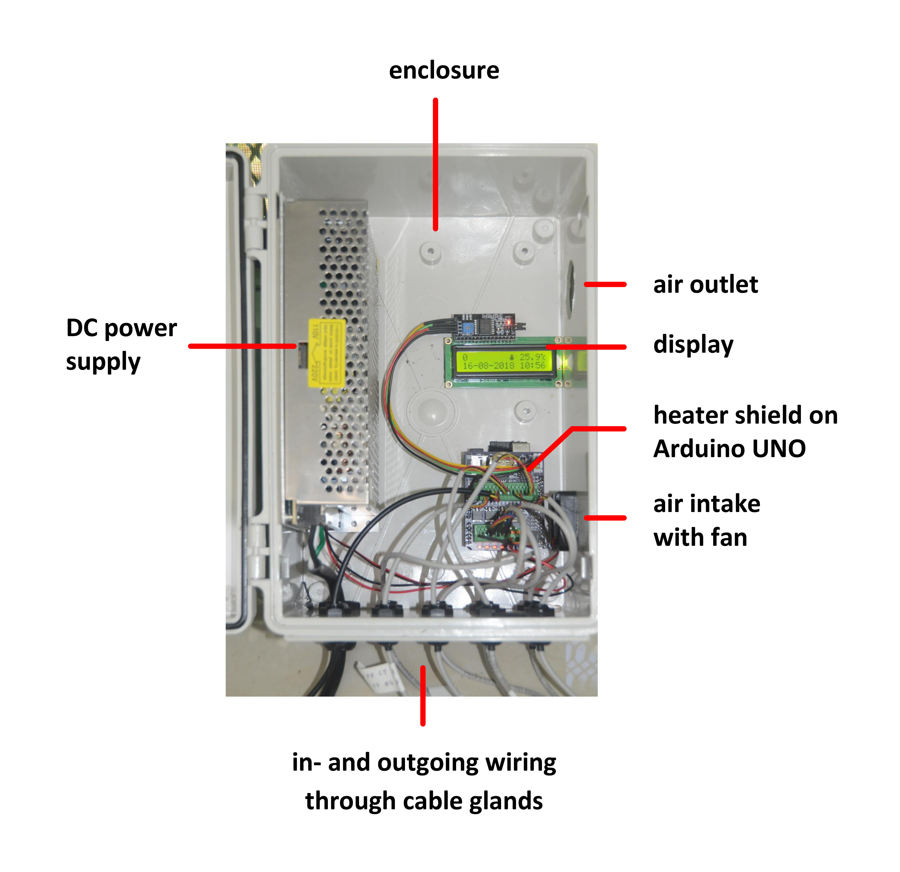
Two 40mm holes were drilled in the right-hand side of the box. A 24VDC 40mm fan aligned over the lower opening draws in cool air which flows over the shield providing forced cooling. The upper opening functions as air outlet. Both openings have a fine mesh over them to keep out debris and ideally have some type of cover to prevent water ingress.
All connections of heater elements and sensors located outside the box are soldered, conformally coated and covered in a double sleeve of marine grade shrink sleeve to seal out moisture.
You need to have the Arduino IDE installed to compile and upload code to the Arduino UNO. If your new to this, check out this Getting Started Page. You can upload code to the Arduino UNO at any time, but make sure to remove power from the power input connector on the shield before connecting to a computer or bad things may happen.
Once code is uploaded to the board a number of system parameters need to be configured. This is done by placing a plain text file named config.txt with configuration data on the SD card and powering up the system. The configuration info will be read from the card and stored permanently. The configuration data should follow the format below EXACTLY (omitting everything in brackets).
dd-mm-yyyy hh:mm:ss                  (system time)
systemID                             (8 characters max)
xxxx.xx                              (Kp parameter)
xxxx.xx                              (Ki parameter)
xxxx.xx                              (Kd parameter)
xxxx                                 (windup limit)
xxxx                                 (upper T limit)
HHHHHHHHHHHHHHHH                     (sensor address for ambient reference)
HHHHHHHHHHHHHHHH,xx.xx               (with target deltaT for heater A)
HHHHHHHHHHHHHHHH,xx.xx               (same heater B)
HHHHHHHHHHHHHHHH,xx.xx               (same heater C)
HHHHHHHHHHHHHHHH,xx.xx               (same heater D)
The first configuration item is the system time used to set the system clock. The systemID allows to assign a 8 character ID to a system which is included in the header of data files, so data can be traced back to a particular unit. The next three values in the configuration file are the main PID tuning parameters Kp, Ki and Kd, followed by a windup limit for the integral error term and an upper temperature limit used to shut down heaters. The next lines specify the 8 byte sensor address (hexadecimal notation) and the targeted temperature increase in degrees centigrade. The IDs of the units are a single character and fixed. We use 0 for the ambient reference sensor and A to D for the heated units corresponding to the silkscreen on the shield. The single character unit IDs can be changed in the functions getConfigSD and getConfigEEPROM in the tab _01_Configuration if desired.
The actual configuration file config.txt will automatically be removed from the card once it is read on start-up. This is done to avoid that date and time are re-initialised on every power-up. All configuration items need to be included in the file, even when only one needs changing. It can therefore be useful to store a backup of the configuration file on the SD card under a different name e.g. configBU.txt. An example of a correctly formatted configuration file can be found in the Documentation.
Note: The hexadecimal sensor address should only contain digits 0-9 and capital letters A-F and be exactly 16 characters long. No check for invalid addresses is implemented, but the unit will halt with a sensor error.
And a note on PID tuning: Depending on the target, heater arrangement and other factors, the PID loop parameters will need to be changed to get (close to) the desired system behaviour. This is a topic in itself and falls outside the scope of this readme. A good strategy is probably to start with a P-only implementation of the loop (setting Ki and Kd to zero) increasing the value of Kp until you approach the setpoint without much overshoot and/or instability. Then add a Ki action to reduce the error term inherent to P-only systems. Be careful when adding the D-action, as measured temperatures are subject to measurement error or quick fluctuations in some targets. A large D-action causes the control action to become noisy. Smoothing the temperature trend on which the D-action is based could potentially limit this issue. This blog goes with an Arduino PID library and gives some nice background if you want to learn more about PID controllers.
While the Arduino UNO is powered down, place the heater shield on top and double check alignment of the headers. Connect the LCD screen through the 4-pin connector on the shield and insert a CR1220 coin cell to keep the clock going when the main power source is down.
Upload the sketch to the UNO if this hasn't happened already, place an SD card with a valid configuration file and cycle power or reset the UNO. The system will now read the configuration file and store it in non-volatile memory for future use. The following sequence of screens will show the system configuration and settings for individual heater units.
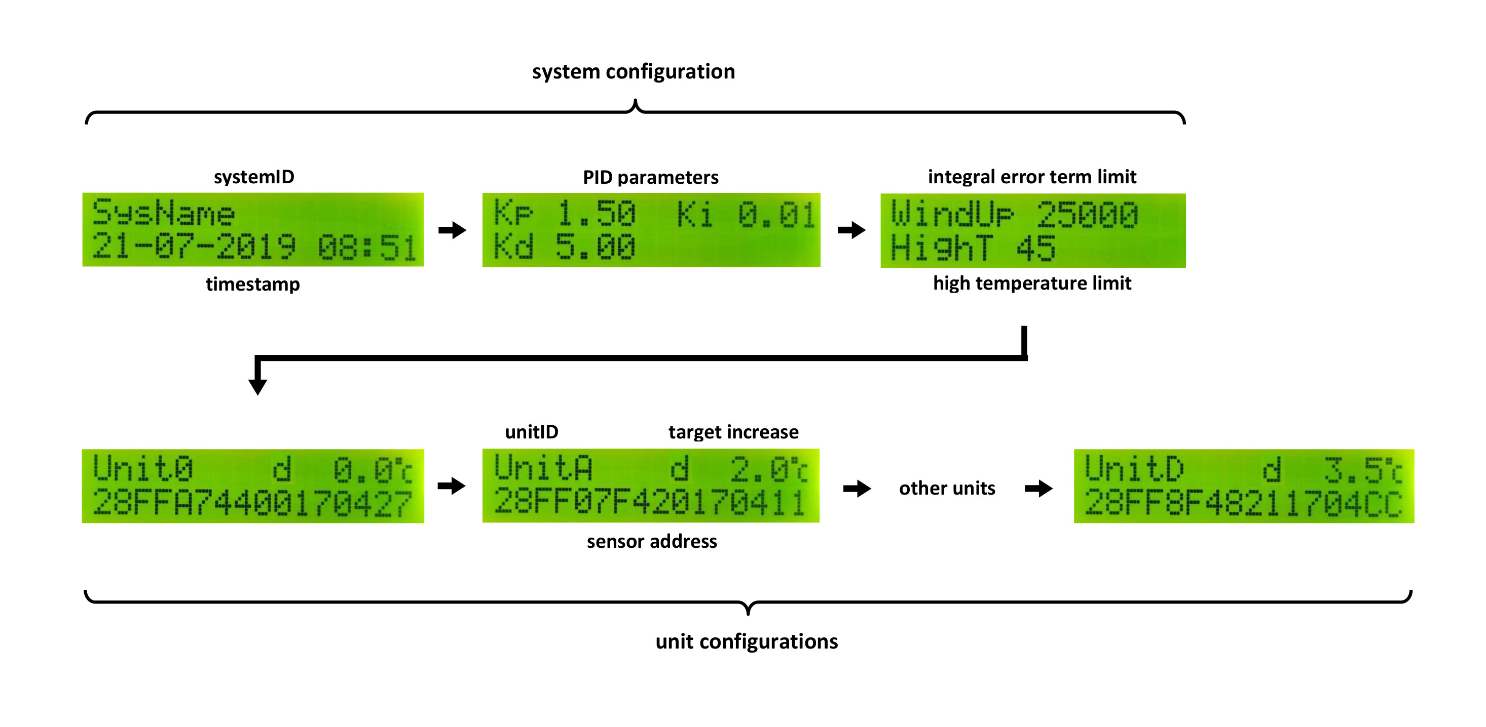
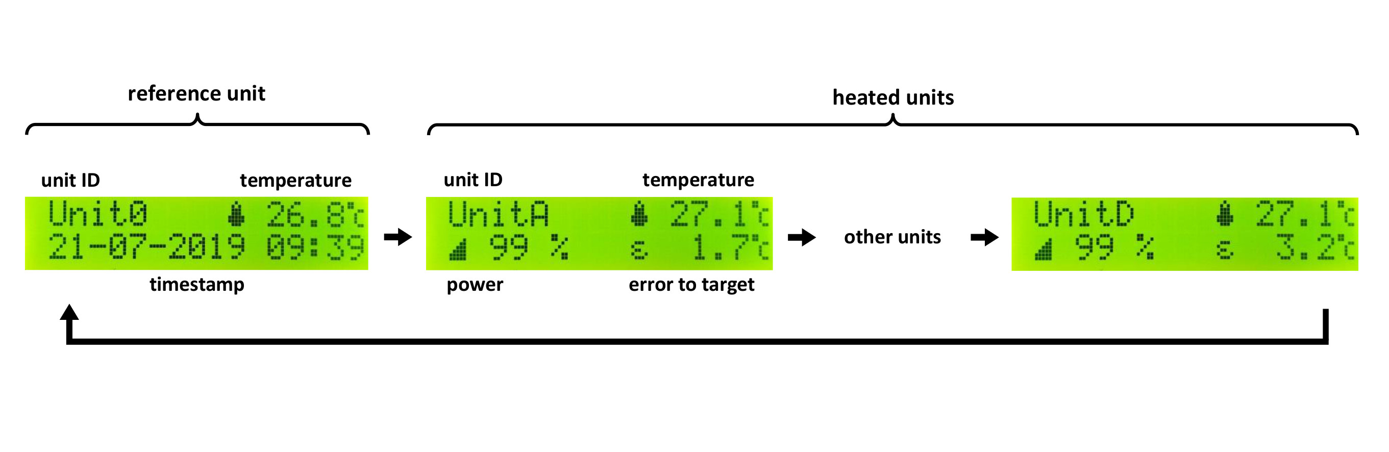
After the configuration info has been displayed the system will start monitoring temperatures and regulate power to each of the four heaters independently to reach the targeted temperature increases. The display rotates through a number of screens showing the current status of the reference sensor and four heated units. For the reference unit the unit ID, temperature and timestamp are shown. For heated units the unit ID, temperature, procentual heater power and error to the target temperature are shown. Activity of each heater is also indicated visually by means of a red LED next to the heater connection. When errors occur the status screen for a given heater unit can be replaced with a warning that that unit has been halted. When system errors occur a screen indicates that the system was halted completely (see Errors).
All data is stored in a single file called datalog.txt. This file is created at start-up and includes a header containing all configuration info. If the file already exists data will be appended. While the system is running temperatures are measured every second, the PID loop is evaluated and heater power adjusted as needed. At one minute intervals a single line of data containing one-minute averages of measured temperatures and procentual heater power is written to file. Sensor errors will result in a NaN temperature value. When a heater unit has been halted the procentual heater power will be set to -99. An example of the header info and a few lines of data is shown below. The first dataline generally contains invalid data as the one-minute interval in which data is collected can be incomplete.
 Start time: 20-07-2019 19:05:52
 System name: SysName
 Kp: 1.50
 Ki: 0.01
 Kd: 5.00
 WindUp: 25000
 HighTemp: 45

 Unit0	0.00	28FFA74400170427
 UnitA	2.00	28FF07F420170411
 UnitB	2.50	28FF74E3011705ED
 UnitC	3.00	28FF9E49211704F2
 UnitD	3.50	28FF8F48211704CC

 TS,T_0,T_A,T_B,T_C,T_D,PWM_A,PWM_B,PWM_C,PWM_D
 (mm/dd/yy hh:mm:ss),(degC),(degC),(degC),(degC),(degC),(%),(%),(%),(%)
 20-07-2019 19:07:00,27.83,27.99,27.80,27.96,28.02,89,89,89,89
 20-07-2019 19:08:00,27.81,28.04,27.80,28.03,28.05,100,100,100,100
 20-07-2019 19:09:00,27.87,28.12,27.86,28.11,28.10,100,100,100,100
 20-07-2019 19:10:00,27.92,28.17,27.91,28.18,28.12,100,100,100,100
 20-07-2019 19:11:00,27.95,28.23,27.93,28.24,28.16,100,100,100,100
 20-07-2019 19:12:00,28.00,28.25,27.97,28.28,28.18,100,100,100,100
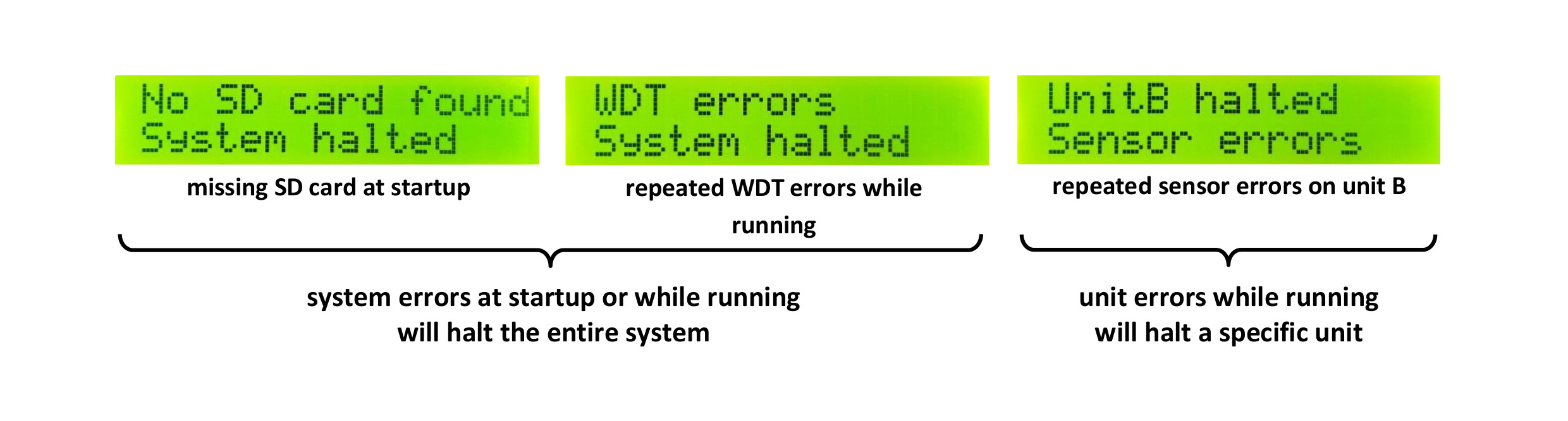
...The system keeps track of different errors that may occur and shuts down the entire system or individual channels if needed. Heater units will be switched off and a warning will appear on the display. The following errors may occur:
The first two errors will immediately halt the system on start-up. This is the case when no SD card is detected or when both internal memory and SD card contain no configuration info.
Sensor errors occur when a temperature sensor does not respond or data is corrupted. Limit errors indicate that the measured temperature exceeded the HighTemp limit specified in the configuration. Both error types have associated counters to track the number of times an error occurred for each individual heater unit. If five or more errors of a given type occur the offending unit is halted and a warning displayed. Error counters are reset at midnight unless excessive errors occurred to prevent shutdowns due to glitches. The number of allowable errors can be set in _06_PIDunit.cpp.
SD card and WDT errors are system level errors. Five SD card errors or 60 WDT errors will trigger a system halt where all heaters shut down. Logging ends and a warning is displayed. The number of allowable errors can be set in _02_Control.cpp.
Below some of the error messages that may appear.
Note: A very crude check is implemented to see if a system was ever configured. If not, and no configuration is found on the SD card the system is halted at start-up.
Removing SD cards while files are kept open for writing or data is being written to the card could lead to corruption of the card and loss of data. The system only writes data to the card at the end of each minute and closes the data file almost immediately after. This will coincide with the display changing over to show info for the reference unit Unit0. Give the system a few seconds to finalize pending card writes and remove the card. Follow the same procedure when removing power from the system. We have never had issues removing cards/power this way, but ideally a card eject button is implemented to safely remove cards at all times.
One thing to keep in mind when modifying (read adding) code to this system is the limited amount of SRAM available on the microcontroller. Of the available 2048 bytes of SRAM close to 1300 are used by global variables. During parts of the setup most of the remaining SRAM is used and available SRAM drops to less then 30 bytes. Additional code can easily cause the controller to run out of SRAM at which point weird and wonderful things start happening. Keep this in mind if code changes lead to 'inexplicable' errors. This Adafruit tutorial gives a nice overview of the issue.
Depending on platform and locale the timestamps logged to the SD card may not be interpreted correctly (e.g. when opening files in a spreadsheet). The code formats the date in timestamps as dd-mm-yyyy. You can modify the function formatTimeDate in the code tab _07_Miscellaneous.ino to format timestamps as desired. This will affect formatting on SD files and LCD. If you also wish to change the timestamp formatting of the configuration routines, you will have to change the getConfigSD function in the tab _01_Configuration.
The system described above uses a DC power supply running of the mains supply. However, any other DC power source such as batteries or a solar system can be used as well. This is especially feasable for low power heater applications. The DC supply (typically 12 or 24V, maximum 28V) can be supplied via the shield power input connector. Make sure to add a suitable fuse to the incoming power lines and that the source can provide sufficient power for the heater configuration over the required duration.
This code is likely not going to be maintained very actively, so feel free to fork this repo for further development. However, I would like to hear back if you find code errors, have suggestions to improve the documentation or simply to learn how you have been using this system.
Copyright Diego Dierick 2019.
The design documentation (including this readme.md) for the PWM heater shield is licensed under CERN OHL v1.2. See cern_ohl_v_1_2.pdf in the DesignDocs folder for the full license. You may redistribute and modify this documentation under the terms of the CERN OHL v.1.2. This documentation is distributed WITHOUT ANY EXPRESS OR IMPLIED WARRANTY, INCLUDING OF MERCHANTABILITY, SATISFACTORY QUALITY AND FITNESS FOR A PARTICULAR PURPOSE. Please see the CERN OHL v.1.2 for applicable conditions.
The firmware (Arduino sketch) is free software: you can redistribute it and/or modify it under the terms of the GNU General Public License as published by the Free Software Foundation, either version 3 of the License, or (at your option) any later version. This program is distributed in the hope that it will be useful, but WITHOUT ANY WARRANTY; without even the implied warranty of MERCHANTABILITY or FITNESS FOR A PARTICULAR PURPOSE. See the GNU General Public License for more details. You should have received a copy of the GNU General Public License along with this program. If not, see http://www.gnu.org/licenses/. See COPYING.md in the Documentation folder for the full GNU license.
| Qty | Value | Footprint | References |
|---|---|---|---|
| 4 | 10k | Resistors_SMD:R_0805 | R1, R2, R3, R4 |
| 4 | LED | LEDs:LED_0805 | A, B, C, D |
| 4 | NMOS_GDSD | TO_SOT_Packages_SMD:TO-252-3_TabPin2 | Q1, Q2, Q3, Q4 |
| 3 | 4k7 | Resistors_SMD:R_0805 | R6, R7, R8 |
| 2 | 100nF | Capacitors_SMD:C_0805 | C3, C5 |
| 2 | 10uF | Capacitors_SMD:C_1206 | C1, C4 |
| 1 | PIDheaterUnoShield:CR1220inv7x2.5mm | CR1220inv7x2.5mmHiRes | |
| 1 | PIDheaterUnoShield:SDinv3x2.25mm | SDinv3x2.25mm | |
| 1 | 100k | Resistors_SMD:R_0805 | R5 |
| 1 | 1K | Resistors_SMD:R_Array_Convex_4x0603 | RN1 |
| 1 | 1k | Resistors_SMD:R_0805 | R9 |
| 1 | 1uF | Capacitors_SMD:C_0805 | C2 |
| 1 | 32K768 7pF | SensorLogV1.0:CPFB_series_HandSoldering | Y1 |
| 1 | ARDUINO_SHIELD | FT:ARDUINO_SHIELD | SHIELD1 |
| 1 | CD4050 | Housings_SOIC:SOIC-16_3.9x9.9mm_Pitch1.27mm | U2 |
| 1 | CR1220 | SensorLogV1.0:BK-916-TR | BT1 |
| 1 | Heaters | PIDheaterUnoShield:Phoenix_PTSA-Z_8pos_2.5mm_1990067 | J2 |
| 1 | I2C_LCD | Connectors_JST:JST_XH_B04B-XH-A_04x2.50mm_Straight | J4 |
| 1 | LOGO | PIDheaterUnoShield:Agami2Inv5x9mm | G*** |
| 1 | MCP1703A-3302/CB | TO_SOT_Packages_SMD:SOT-23 | U1 |
| 1 | Molex_47219001_HingedMicroSD | SensorLogV1.0:Molex_47219001_HingedMicroSD | CON1 |
| 1 | OneWire | PIDheaterUnoShield:Phoenix_PTSA-Z_16pos_2.5mm_1990148 | J3 |
| 1 | PCF8523 | Housings_SOIC:SOIC-8_3.9x4.9mm_Pitch1.27mm | U3 |
| 1 | PWR_IN | PIDheaterUnoShield:Phoenix_SPTAF_2pos_3.5mm_1862042 | J1 |
| 1 | R-78E5.0-0.5 | Converters_DCDC_ACDC:DCDC-Conv_RECOM_R-78E-0.5 | U4 |
The 38 most common of 40 parts.
It measures 68.6 × 53.3 mm and has 2 copper layers, 1.6 mm thick.
40 parts, built around the CD4050BD, R-78E5.0-0.5, PCF8523T and CR1220-2. The full list of its parts is on this page, with links to each part's symbol and footprint where PCBKit's library has them.
From the diegodierick/Heater-shield repository on GitHub, at the commit this page was made from: the board is DesignDocs/KiCad/PIDheaterUnoShield.kicad_pcb. PCBKit opens the board in the browser, with nothing to install.
Its repository states no licence, so its author keeps all rights: ask diegodierick before reusing the design.


LadyRoninEngineer/Si473x
Data Supporting development of Si473x series radios


lisasnt/Position-and-Temperature-Controller
Embedded Systems BSs course Project


