2 layers65 × 106.5 mm
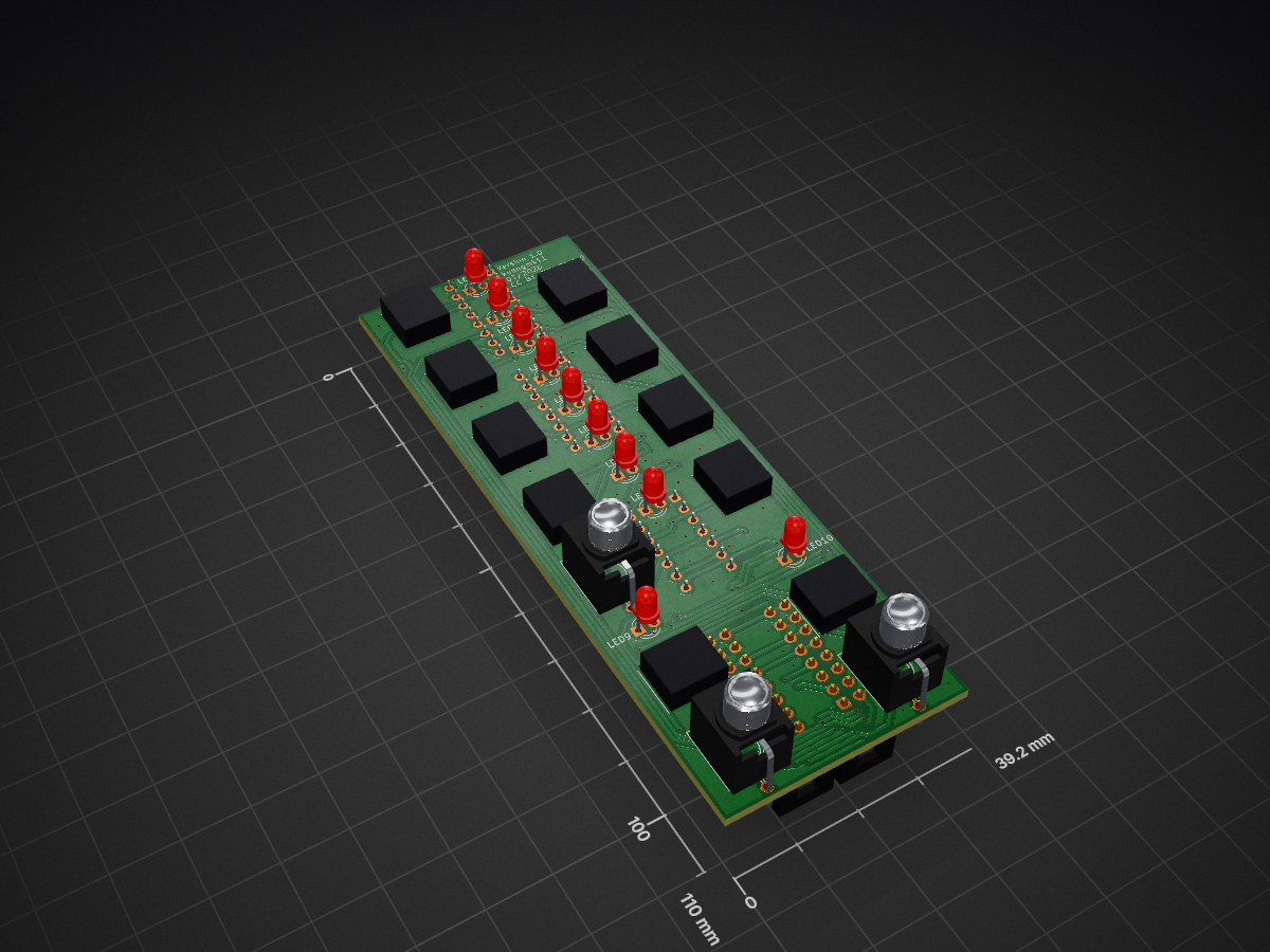
 MissingMileModular/Doubleplus_Pulses
Turing Machine Expander
Pulses plus submin is an open-source printed circuit board by MissingMileModular, from the MissingMileModular/Doubleplus_Pulses repository on GitHub. It is a 2-layer board of 39.2 × 110 mm with 87 parts on 89 nets, routed with 556 tracks and 113 vias.
It is built around the CD4050BD, CD40106 and MMBT3904. Its parts include 43 diodes, 21 resistors, 10 switches, 5 connectors and 4 capacitors.


A performance-oriented gate router for the Music Thing Turing Machine. Eight pulse channels, each switchable to one of two merge buses or off; each bus computes the OR or the AND of whatever is routed to it, chosen live from the panel.
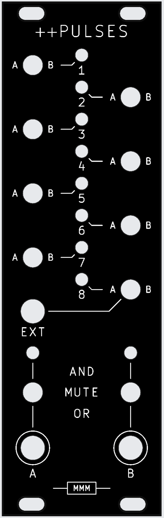
Built and tested. 8 HP, 128.5 × 40.16 mm.
It sits alongside a stock Pulses expander rather than replacing it, taking its signals from the Turing Machine's 16-pin expander ribbon and passing that ribbon through so other expanders can still be chained downstream.
The stock Pulses gives you seven fixed outputs plus four hard-wired AND combinations. Those AND outputs are the musical ones — ANDing two shift-register taps gives a sparser, related rhythm. This generalises that: any subset of the eight bits, OR'd or AND'd, chosen by hand, live. The four fixed ANDs become a strict subset of what the switches can do.
pulses_plus_submin.kicad_sch | schematic — 87 placed components |
pulses_plus_submin.kicad_pcb | main board |
pulses_plus_submin_panel_v4.kicad_pcb | current panel |
pulses_plus_submin_panel.kicad_pcb | v1 panel — the geometry source build_panel.py inherits holes from |
pulses_plus_submin.pretty/ | project footprints — toggle, jack, LED, panel holes |
switch_fix.kicad_sym | the DPDT symbol with the pin numbering the footprint expects |
3d/ | 3D models the footprints reference |
BOM.md | bill of materials, DigiKey and JLCPCB/LCSC columns |
BOM_DigiKey.csv | the same BOM as a DigiKey cart upload |
gerbers/ | fab packages — see below |
tools/build_panel.py | regenerates the panel artwork |
PANEL_STYLE_v1.12.md | the panel house style |
docs/pulses-plus-design.md | full design write-up, including the diode-leak analysis and why 6 HP was abandoned |
docs/sw-t2-4x-b-a2-ma2-data-sheet.pdf | Taiway 200-MDP3 toggle datasheet |
gerbers/ accumulated every revision that was sent out. The panel to order is
gerbers/panelv4.rar. For the board:
gerbers_v2/ — current plot of pulses_plus_submin_v2.kicad_pcb, including C5/C6
(see the erratum below). Not yet fabbed.gerbers/controlv2.zip — what was actually fabbed and built. Boards from this package
predate C5/C6 and need the two-capacitor rework.The loose .gbr/.drl files at the top of gerbers/ are the most recent plot of the
main board and the v1/v2 panels, kept unzipped for inspection.
Any board built without C5/C6 needs a two-capacitor rework.
Symptom. On the step after a real trigger — a step where the bus should be silent — a downstream envelope fires an extra time. The bus LED never visibly flashes, and the same envelope behaves correctly on the Turing Machine's own pulse output and on a stock Pulses. A Kassutronics ASR is the known case; the affected class is any gate input that triggers on the rising edge at a low threshold (the ASR's fires from ~+1.2 V).
Cause. The Turing Machine's expander bits are stage AND clock, and the clock's rising edge
opens that AND before the shift register has finished shifting — so the ribbon briefly presents the
previous step's pattern. This module's two cascaded CD40106 Schmitt buffers then regenerate that
soft sub-µs bump into a sharp, near-full-amplitude micro-gate. Full analysis in
docs/pulses-plus-design.md.
Fix. Tack a 4.7 nF ceramic on top of R15, and another on top of R16. Those 1206 pads
are already BUSA_SEL→GND and BUSB_SEL→GND on the back of the board, so there are no trace cuts,
no lifted pins, and it is fully reversible. Verified on hardware.
pulses_plus_submin_v2.*) as C5/C6. The v1 files do not
have it.Each channel's DPDT ON-OFF-ON toggle throws left to bus A, right to bus B, or centre for off. Both poles are used: pole 1 carries only the OR diodes, pole 2 only the AND diodes. That separation is the one non-obvious constraint in the design — sharing a pole leaks current through the unselected bus and pins its OR net high.
Per bus, a second toggle picks OR, MUTE or AND. Both nets are computed continuously and in parallel, so the mode switch only selects which one reaches the output buffer and the 32 merge diodes never switch. Centre-off leaves the buffer input pulled low, which is the mute.
The EXT jack is switched (normalled): unplugged, buffered BIT8 feeds channel 8; plugged, an external gate takes its place through a transistor and Schmitt stage that squares up whatever amplitude arrives.
Full write-up: docs/pulses-plus-design.md.
The two buses are two independent reads of the same shift register. Whatever either one plays is built from the same eight bits on the same loop, so they cannot drift apart — but give them different channels, or put one in AND and the other in OR, and they come out at different densities. Related, never identical. Most of the musical mileage is in that gap.
The patch this turned out to be best at, and not one it was designed for:
The quantizer only samples when bus B fires, so the note is held across every gate bus A produces in between. A melody moves on its own slow rhythm while the gates articulate underneath — and because both rhythms are subsets of one register, the note changes land on beats the gate pattern already stresses. It reads as a phrase, not as two voices running at once.
Being a Turing Machine underneath, the loop-length and randomness controls then act on the whole thing at once: lock the register for a repeating riff, open it a crack and the melody mutates while staying in its scale.
Pulse width passes straight through. The board is purely combinational: it merges what arrives on the ribbon and never looks at the clock. It does not need to — the Turing Machine's expander bus already carries each bit ANDed with the clock, so the bits arrive as pulses, and the diode merge preserves their width. Feed the TM a narrow clock and the outputs are narrow; feed it a wide one and they are wide, all the way to OUT A and OUT B.
So an AND that is true on three consecutive steps gives three pulses, one per step — each re-triggering the envelope or re-pinging the quantizer, rather than merging into one long gate. The note changes on every step the condition holds, which is why choosing a condition that comes true rarely is what makes the melody move slowly.
Things to reach for:
10 × Taiway 200-MDP3 sub-miniature DPDT ON-OFF-ON toggles (ø4.95 bushing), 2 × CD4050 buffers,
1 × CD40106 Schmitt, 33 × 1N4148, 10 × 3 mm LEDs, 3 × Thonkiconn jacks — J3 must be the
switched variant — and 2 × 2×8 IDC headers for ribbon in and thru. See BOM.md.
The current panel is v4, pulses_plus_submin_panel_v4.kicad_pcb — white silkscreen on black
soldermask, drawn to PANEL_STYLE_v1.12.md.
It is generated. tools/build_panel.py reads the v1 panel and regenerates
only the artwork, inheriting every control-hole position, so the style guide's one non-negotiable
rule — hole positions are inherited, never computed — holds by construction rather than by
inspection:
python3 tools/build_panel.pyMounting is four 6.4 × 3.2 mm obround slots on Edge.Cuts, horizontal for ±1.6 mm of slide.
kicad-cli pcb drc reports zero violations. Zones refill on open — refill before plotting.
Reading the panel: a ring means signal leaves there, so the two output jacks are the only closed
circles. A/B beside each toggle are throw directions, not names. The mode stack is AND up,
MUTE centre, OR down. Names sit below the thing they name.
CC BY-NC-SA 4.0 — see LICENSE.
| Qty | Value | Footprint | References |
|---|---|---|---|
| 33 | 1N4148 | Diode_SMD:D_SOD-123 | D1, D2, D10, D11, D12, D13, D14, D15, D16, D17, D18, D19, D20, D21, D22, D23 +17 |
| 10 | 4k7 | Resistor_SMD:R_1206_3216Metric_Pad1.30x1.75mm_HandSolder | R1, R2, R3, R4, R5, R6, R7, R8, R9, R10 |
| 10 | LED | LED_THT:LED_D3.0mm | LED1, LED2, LED3, LED4, LED5, LED6, LED7, LED8, LED9, LED10 |
| 8 | DPDT ON-OFF-ON | pulses_plus_submin:SW_200_MDP3_DPDT | SW1, SW2, SW3, SW4, SW5, SW6, SW7, SW8 |
| 6 | 10k | Resistor_SMD:R_1206_3216Metric_Pad1.30x1.75mm_HandSolder | R11, R12, R13, R14, R19, R21 |
| 3 | 100n | Capacitor_SMD:C_1206_3216Metric_Pad1.33x1.80mm_HandSolder | C1, C2, C3 |
| 2 | 1M | Resistor_SMD:R_1206_3216Metric_Pad1.30x1.75mm_HandSolder | R15, R16 |
| 2 | 1k | Resistor_SMD:R_1206_3216Metric_Pad1.30x1.75mm_HandSolder | R17, R18 |
| 2 | CD4050 | Package_DIP:DIP-16_W7.62mm | U1, U2 |
| 1 | 10u | Capacitor_SMD:C_1206_3216Metric_Pad1.33x1.80mm_HandSolder | C4 |
| 1 | 22k | Resistor_SMD:R_1206_3216Metric_Pad1.30x1.75mm_HandSolder | R20 |
| 1 | CD40106 | Package_DIP:DIP-14_W7.62mm | U3 |
| 1 | CHAIN THRU | Connector_IDC:IDC-Header_2x08_P2.54mm_Vertical | J2 |
| 1 | EXT | pulses_plus_submin:Thonkiconn_PJ301M | J3 |
| 1 | MMBT3904 | Package_TO_SOT_SMD:SOT-23 | Q1 |
| 1 | OR/MUTE/AND A | pulses_plus_submin:SW_200_MDP3_DPDT | SW9 |
| 1 | OR/MUTE/AND B | pulses_plus_submin:SW_200_MDP3_DPDT | SW10 |
| 1 | OUT A | pulses_plus_submin:Thonkiconn_PJ301M | J4 |
| 1 | OUT B | pulses_plus_submin:Thonkiconn_PJ301M | J5 |
| 1 | PULSES IN EITHER HEADER | Connector_IDC:IDC-Header_2x08_P2.54mm_Vertical | J1 |
It measures 39.2 × 110 mm and has 2 copper layers, 1.6 mm thick.
87 parts, built around the CD4050BD, CD40106 and MMBT3904. The full list of its parts is on this page, with links to each part's symbol and footprint where PCBKit's library has them.
From the MissingMileModular/Doubleplus_Pulses repository on GitHub, at the commit this page was made from: the board is pulses_plus_submin.kicad_pcb and its schematic pulses_plus_submin.kicad_sch. PCBKit opens the board in the browser, with nothing to install.
Its repository states no licence, so its author keeps all rights: ask MissingMileModular before reusing the design.

diegodierick/Heater-shield
This repository contains code and design files for a four channel Arduino based heater.

lisasnt/Position-and-Temperature-Controller
Embedded Systems BSs course Project


michd/esp32-wled-level-shifter
PCB connecting ESP32 dev board and level shifter for hookup to 5V APA102 LED strip