Skip to the content
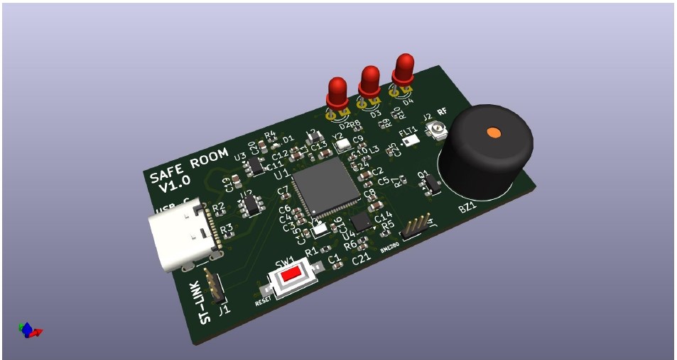
4 layers55.5 × 32 mmSAFE ROOM, the printed circuit board in 3D

SAFE ROOM est une dispositif électronique qui permet de connaitre en temps réel, les conditions d'une pièce. A savoir la qualité d'air, la temperature, l'humidité, et la pression. Ce projet intègre également une antenne bluetooth qui permet de transmettre sur une platform les données capteur.

Size
55.5 × 32 mm
Copper layers
4
Thickness
1.62 mm
Parts
52
Nets
77
Pads
214
Tracks, vias
415, 95
Pours
3
Routed
Yes
KiCad
KiCad 9.0 (file 20241229)
Created
5 May 2026
Updated
19 Oct 2026

Overview

SAFE ROOM is an open-source printed circuit board by dibreyjonatan, from the dibreyjonatan/SAFE-ROOM repository on GitHub, published under the GPL-3.0 licence. It is a 4-layer board of 55.5 × 32 mm with 52 parts on 77 nets, routed with 415 tracks and 95 vias.

It is built around the STM32WB55RGV6, DLF162500LT-5028A1 and BME280, with the MIC5365-3.3YD5-TR, USBLC6-2SC6 and 04023C104KAT2A among its other parts. Its parts include 21 capacitors, 10 resistors, 4 ICs, 4 diodes and 4 connectors. It belongs with the STM32 boards of this library.

Main components

12

README

README.md

SAFE-ROOM

SAFE ROOM est une dispositif électronique qui permet de connaitre en temps réel, les conditions d'une pièce. A savoir la qualité d'air, la temperature, l'humidité, et la pression. Ce projet intègre également une antenne bluetooth qui permet de transmettre sur une platform les données capteur.

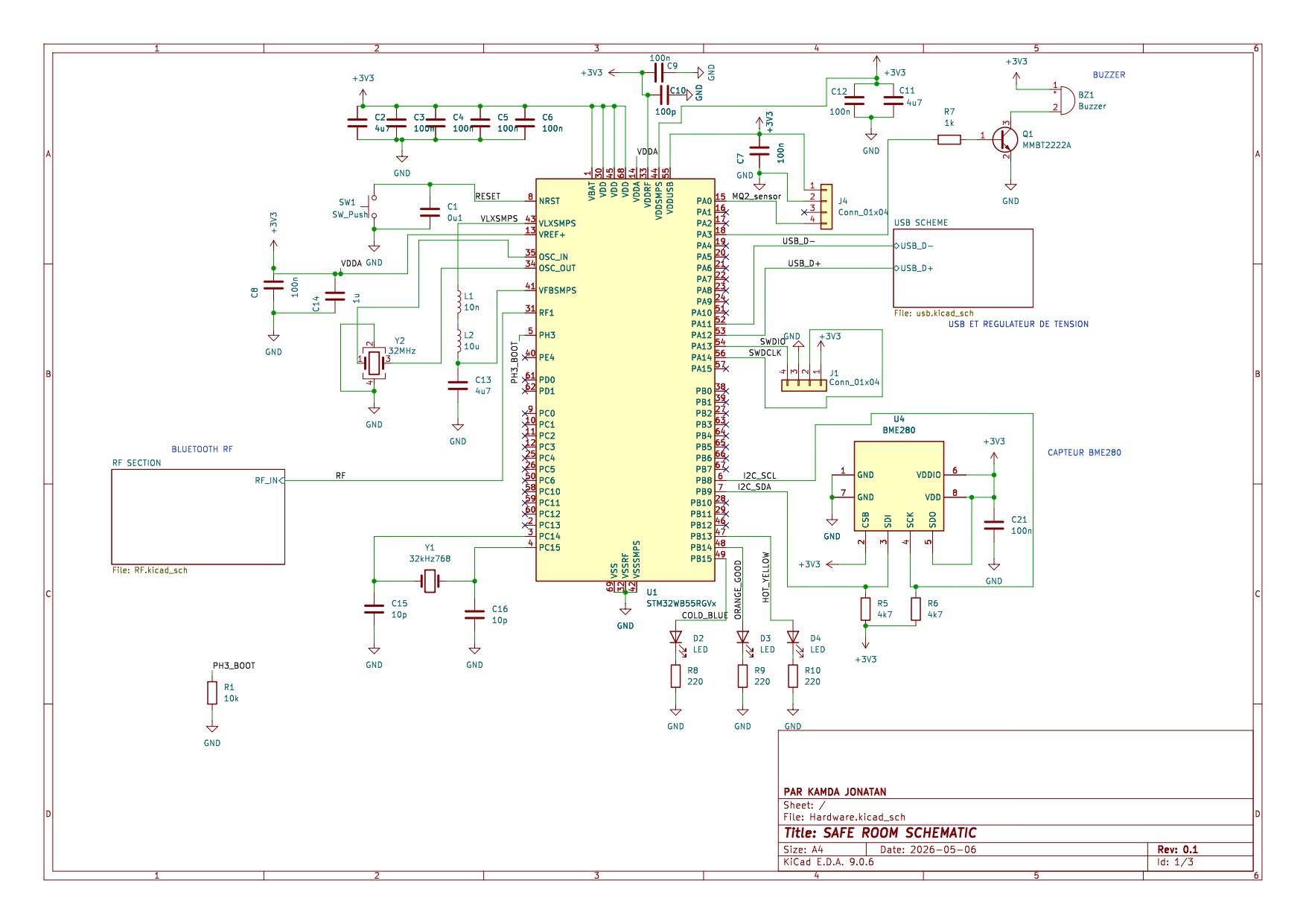
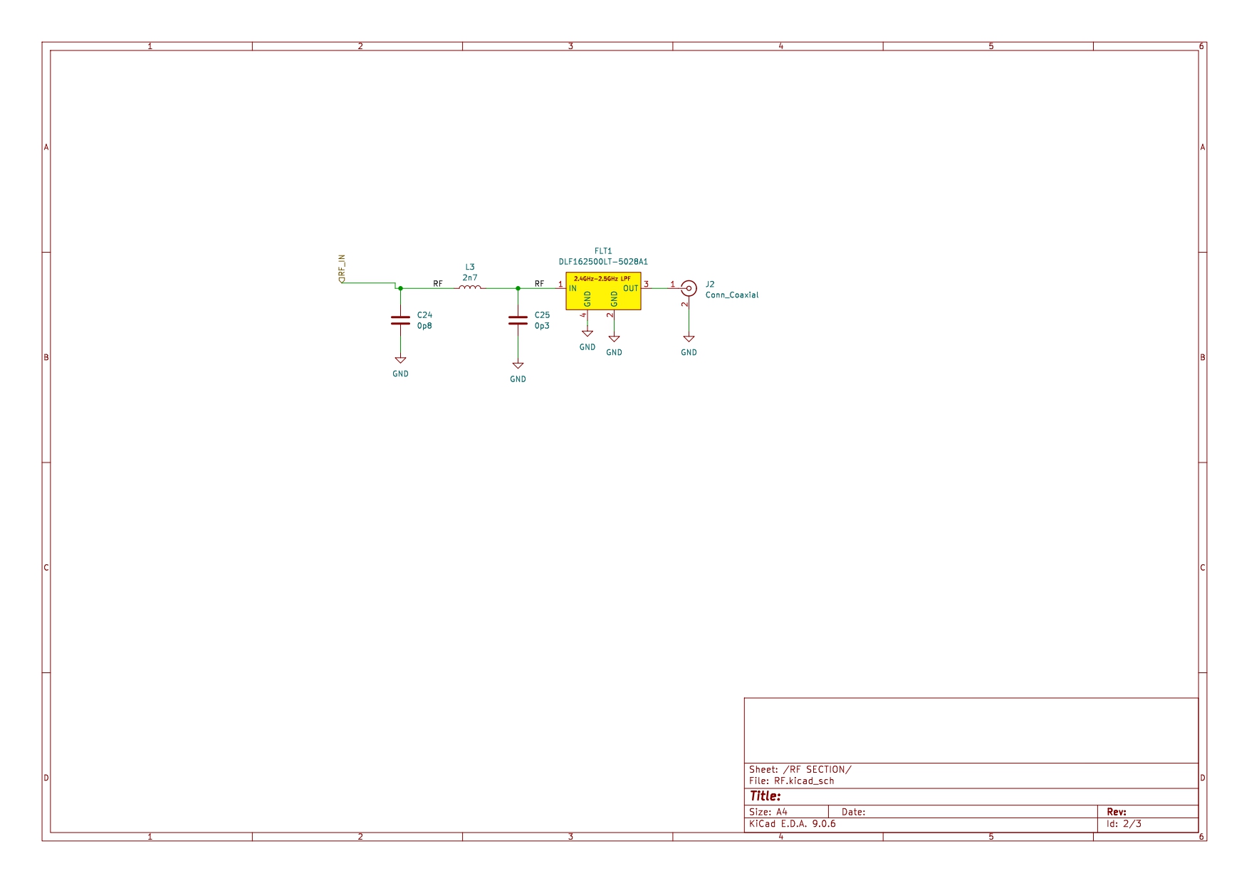
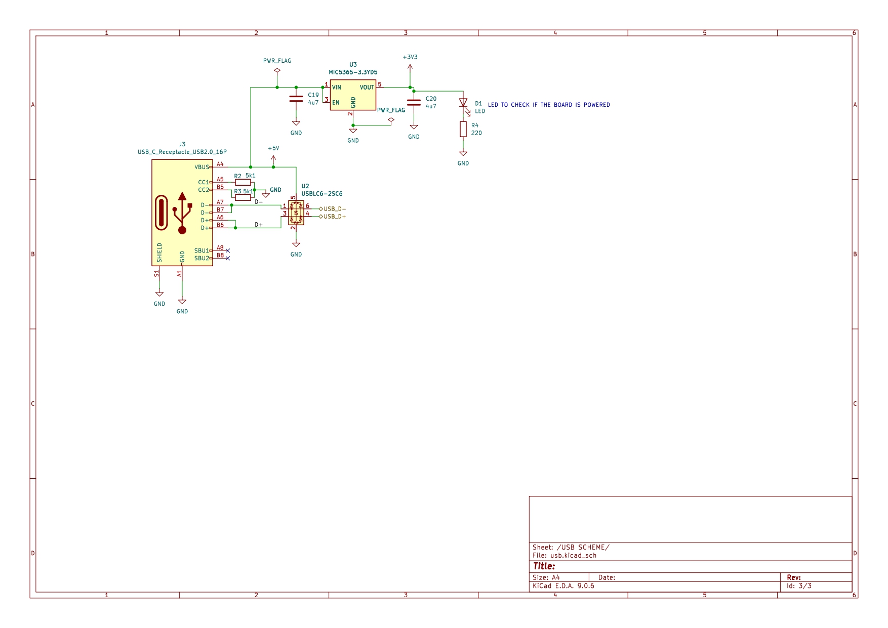
SCHEMATIQUE DU PROJET

La schématique a été réalisé avec KiCAD 9.0 schematic_system schematic_rf schematic_usb

CARTE SAFE ROOM

pcb_finale

Parts

52
QtyValueFootprintReferences
9100nCapacitor_SMD:C_0402_1005MetricC3, C4, C5, C6, C7, C8, C9, C12, C21
54u7Capacitor_SMD:C_0603_1608MetricC2, C11, C13, C19, C20
4220Resistor_SMD:R_0402_1005MetricR4, R8, R9, R10
3LEDLED_THT:LED_D3.0mmD2, D3, D4
210pCapacitor_SMD:C_0402_1005MetricC15, C16
24k7Resistor_SMD:R_0402_1005MetricR5, R6
25k1Resistor_SMD:R_0402_1005MetricR2, R3
2Conn_01x04Connector_PinHeader_2.54mm:PinHeader_1x04_P2.54mm_VerticalJ1, J4
10p3Capacitor_SMD:C_0402_1005MetricC25
10p8Capacitor_SMD:C_0402_1005MetricC24
10u1Capacitor_SMD:C_0402_1005MetricC1
1100pCapacitor_SMD:C_0402_1005MetricC10
110kResistor_SMD:R_0402_1005MetricR1
110nInductor_SMD:L_0402_1005MetricL1
110uInductor_SMD:L_0805_2012MetricL2
11kResistor_SMD:R_0402_1005MetricR7
11uCapacitor_SMD:C_0402_1005MetricC14
12n7Inductor_SMD:L_0402_1005MetricL3
132MHzCrystal:Crystal_SMD_2016-4Pin_2.0x1.6mmY2
132kHz768Crystal:Crystal_SMD_2012-2Pin_2.0x1.2mmY1
1BME280Package_LGA:Bosch_LGA-8_2.5x2.5mm_P0.65mm_ClockwisePinNumberingU4
1BuzzerBuzzer_Beeper:Buzzer_12x9.5RM7.6BZ1
1Conn_CoaxialConnector_Coaxial:U.FL_Hirose_U.FL-R-SMT-1_VerticalJ2
1DLF162500LT-5028A1my_personnal_Library_footprint:FIL_DEA160915LT-1169FLT1
1LEDLED_SMD:LED_0402_1005MetricD1
1MIC5365-3.3YD5Package_TO_SOT_SMD:TSOT-23-5U3
1MMBT2222APackage_TO_SOT_SMD:SOT-23Q1
1STM32WB55RGVxmy_personnal_Library_footprint:QFN40P800X800X100-69NU1
1SW_PushButton_Switch_SMD:SW_SPST_CK_RS282G05A3SW1
1USBLC6-2SC6Package_TO_SOT_SMD:SOT-23-6U2
1USB_C_Receptacle_USB2.0_16PConnector_USB:USB_C_Receptacle_GCT_USB4105-xx-A_16P_TopMnt_HorizontalJ3

Similar boards

  • 4 layers48 × 25 mmStm32mc, the printed circuit board in 3D

    Stm32mc

    justinfederico/STM32testPCB

    Custom STM32WB microcontroller to practice my PCB schematic and layout skills. Looking to get it printed soon! Bear in mind that this is an ameuter project, so there will probably be errors aplenty.

    51 parts
  • 4 layers117 × 77 mmProdDeck, the printed circuit board in 3D

    ProdDeck

    arsovskiteodor/A.ProdDeck

    Open-hardware macro pad (WIP): custom KiCad PCB with keys, encoders and a fader, plus firmware and a desktop configurator

    69 parts
  • 4 layers58 × 38 mmBlue Pedal, the printed circuit board in 3D

    Blue Pedal

    Arre-Jay/BlueWavePCB

    Untested bluetooth and IMU board with USB input

    80 parts3
  • 4 layers52 × 25 mmFlying byte v1, the printed circuit board in 3D

    Flying byte v1

    PanBabinicz/ghost-feather

    Here: - -n myenv specifies the environment name - python=3.10 installs a specific Python version

    52 parts
  • 2 layers60 × 78 mmSTM32WB breakout board, the printed circuit board in 3D

    STM32WB breakout board

    pho3nix06/PCB_Design_project

    Repository for PCB designed by myself

    42 parts
  • 4 layers30 × 30 mmWearable imu, the printed circuit board in 3D

    Wearable imu

    davispe1/wearable-imu

    Node PCB — revision 1.0. 4-layer board (F.Cu, In1.Cu, In2.Cu, B.Cu).

    72 partsMIT
  • 2 layers100 × 65 mmAstroplant AL, the printed circuit board in 3D

    Astroplant AL

    AstroPlant/astroplant-hardware

    Raw data files for hardware PCB's

    102 parts3
  • 4 layers100 × 30 mmNrst tracks only, the printed circuit board in 3D

    Nrst tracks only

    vexpaer/vexpaers_heart

    Open-source Holter ECG recorder hardware: ADS1294R, STM32WB55, microSD, BLE and USB-Pogo dock

    167 partsCERN-OHL-S-2.0

Questions

How big is the SAFE ROOM PCB?

It measures 55.5 × 32 mm and has 4 copper layers, 1.62 mm thick.

What parts does the SAFE ROOM use?

52 parts, built around the STM32WB55RGV6, DLF162500LT-5028A1, BME280 and MIC5365-3.3YD5-TR. The full list of its parts is on this page, with links to each part's symbol and footprint where PCBKit's library has them.

Where can I download the SAFE ROOM KiCad files?

From the dibreyjonatan/SAFE-ROOM repository on GitHub, at the commit this page was made from: the board is Hardware/Hardware.kicad_pcb and its schematic Hardware/Hardware.kicad_sch. PCBKit opens the board in the browser, with nothing to install.

Can I use the SAFE ROOM design in my own project?

Its repository publishes it under the GPL-3.0 licence: you may reuse it on that licence's terms (keep the author's notice, and for a copyleft licence share your changes alike).