
2 layers100 × 100 mm
Mist1010
UzixLS/mist1010-board
10x10cm PCB variant of MIST FPGA project for G738/G706 enclosure
273 parts43MIT
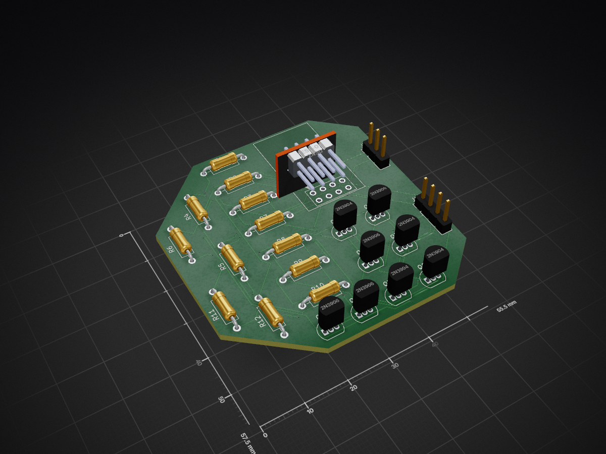
 dialgorithm/tilt
galvanic vestibular stimulation device
Tilt is an open-source printed circuit board by dialgorithm, from the dialgorithm/tilt repository on GitHub. It is a 2-layer board of 55.5 × 57.5 mm with 23 parts on 22 nets, routed with 301 tracks and 56 vias.
It is built around the ESP-01. Its parts include 12 resistors, 8 transistors, 2 connectors and 1 IC. It belongs with the ESP8266 boards of this library.
[!WARNING] This is a hobbyist project that delivers electrical current to the head and vestibular system, and it comes with real risks, always use a properly current-limited circuit (never mains-powered directly), verify output with a meter before any skin contact, and stay well within the safe current thresholds Don't use this device if you're pregnant, have epilepsy, a pacemaker or other implanted electronic device, a heart condition, or any neurological disorder, and stop immediately if you feel pain, burning, severe disorientation, or other adverse effects. This worked for me, but that's no guarantee it'll work the same for you, everyone's setup, wiring, and physiology are different, and things can go wrong. Build and use entirely at your own risk; I'm not liable for any injury, damage, or other consequences from building or using this you're on your own for that.
custom galvanic vestibular stimulation device to control/hack your balance
galvanic vestibular stimulation (gvs) delivers low-current dc signals (1-2 ma) across the mastoid processes to hack your balance. the cathode depolarizes the vestibular nerves to increase their firing rate, while the anode hyperpolarizes them to decrease it. your brain perceives this mismatch as physical tilt, forcing your body to instinctively lean toward the anode to compensate.
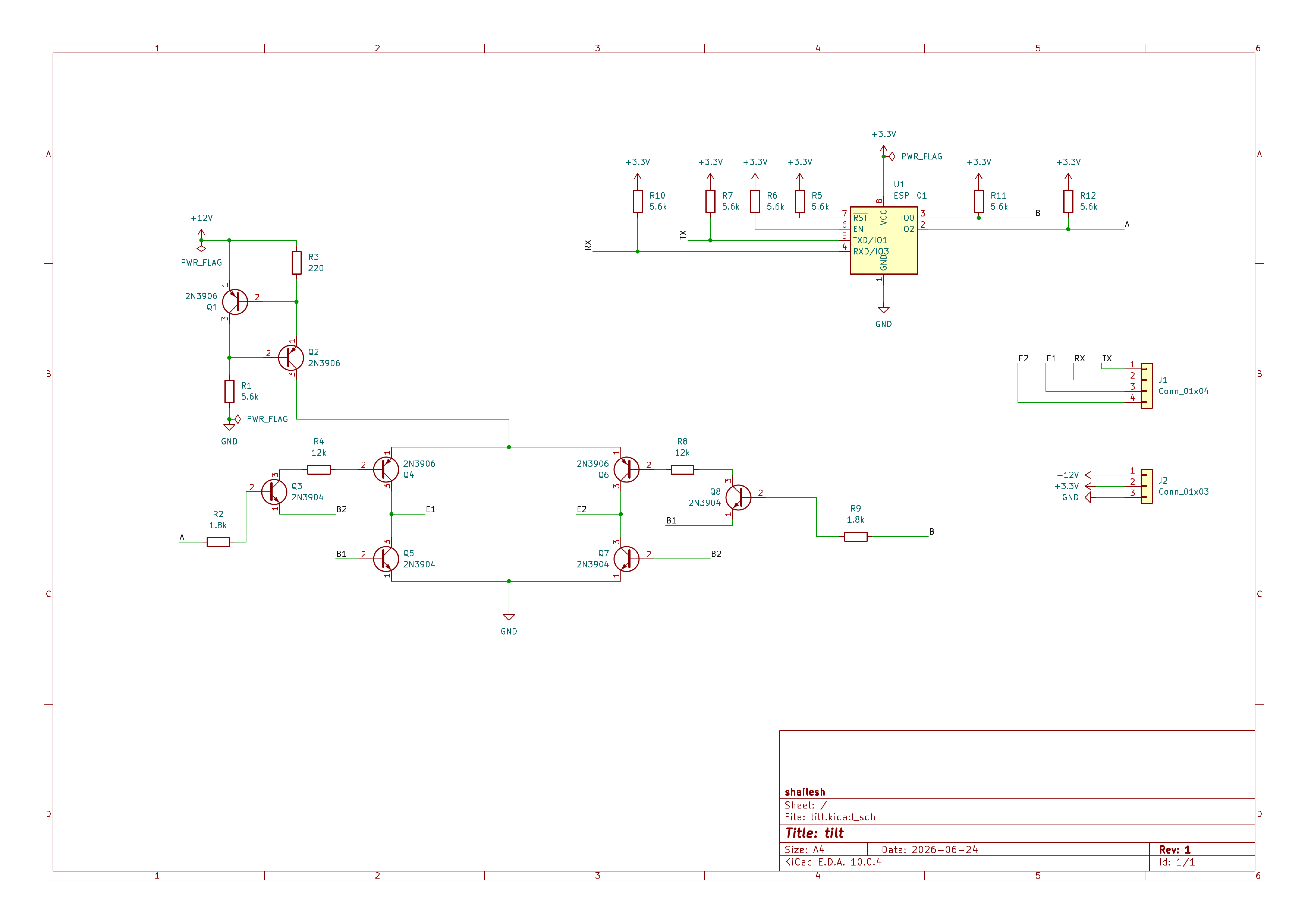
control (esp-01) generates complementary pwm and direction signals. gpio0 and gpio2 need pull-up/pull-down resistors to force a known safe state during bootup so they don't float and trigger the stimulation rail on power-up
power boost (mt3608) steps up 3.7v input to a stable 12v-15v rail. this high headroom is required to break through skin-electrode impedance, which easily sits around 5k-10k ohms on dry skin
galvanic isolation optoisolators decouple the microcontroller's logic from the stimulation stage. this shields your head from any potential mains-side faults or grounding issues if you ever plug the esp-01 into a usb port to debug
active constant-current regulation the critical safety gate. uses an lm334 or a closed-loop feedback op-amp to clamp the current to a strict 1.5ma-2ma. this overrides the dynamic drop in skin resistance so you don't get a sudden, uncontrolled current spike
h-bridge polarity control uses a matched array of 2n3906 (pnp) and 2n3904 (npn) transistors. dynamically reverses the current path across the electrode array, swapping which mastoid acts as the cathode and which acts as the anode for left/right tilt
i just wanted a non rectangular shaped pcb so i just made it into a random polygon
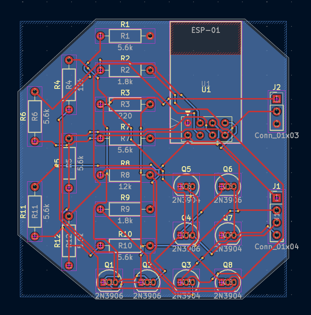
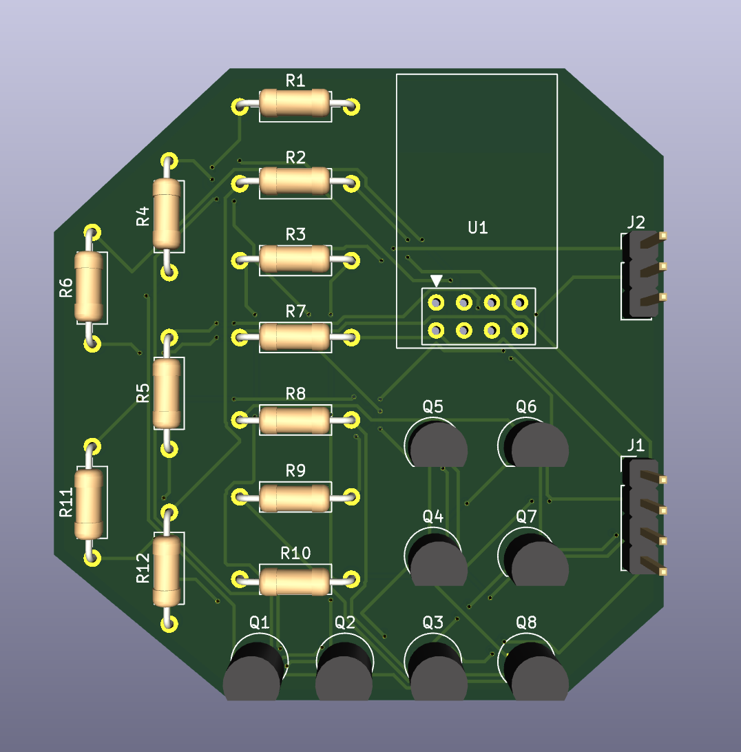
check out the wiki for the build, flashing and firmware instructions for this project.
| Qty | Value | Footprint | References |
|---|---|---|---|
| 7 | 5.6k | Resistor_THT:R_Axial_DIN0207_L6.3mm_D2.5mm_P10.16mm_Horizontal | R1, R5, R6, R7, R10, R11, R12 |
| 4 | 2N3904 | Package_TO_SOT_THT:TO-92_Inline | Q3, Q5, Q7, Q8 |
| 4 | 2N3906 | Package_TO_SOT_THT:TO-92_Inline | Q1, Q2, Q4, Q6 |
| 2 | 1.8k | Resistor_THT:R_Axial_DIN0207_L6.3mm_D2.5mm_P10.16mm_Horizontal | R2, R9 |
| 2 | 12k | Resistor_THT:R_Axial_DIN0207_L6.3mm_D2.5mm_P10.16mm_Horizontal | R4, R8 |
| 1 | 220 | Resistor_THT:R_Axial_DIN0207_L6.3mm_D2.5mm_P10.16mm_Horizontal | R3 |
| 1 | Conn_01x03 | Connector_PinHeader_2.54mm:PinHeader_1x03_P2.54mm_Vertical | J2 |
| 1 | Conn_01x04 | Connector_PinHeader_2.54mm:PinHeader_1x04_P2.54mm_Vertical | J1 |
| 1 | ESP-01 | RF_Module:ESP-01 | U1 |
It measures 55.5 × 57.5 mm and has 2 copper layers, 1.6 mm thick.
23 parts, built around the ESP-01. The full list of its parts is on this page, with links to each part's symbol and footprint where PCBKit's library has them.
From the dialgorithm/tilt repository on GitHub, at the commit this page was made from: the board is kicad/tilt.kicad_pcb and its schematic kicad/tilt.kicad_sch. PCBKit opens the board in the browser, with nothing to install.
Its repository states no licence, so its author keeps all rights: ask dialgorithm before reusing the design.
UzixLS/mist1010-board
10x10cm PCB variant of MIST FPGA project for G738/G706 enclosure

michar71/DMX_CTRL
DMX512 Controller for light installations based on Bluepill STM32F103 Board


Rangarig/MK312WIFI
A replacement for the MK312's bluetooth adapter that allows to connect to it via wifi ... or comport

slemanz/chronolog
STM32-based temperature data logger with RTC, NOR flash storage, LCD and Wi-Fi. Hardware and firmware.

beckdac/uArm-MicroView-esp8266
uArm control PCB with MicroView (Arduino w/ OLED) and esp8266 WiFi/UART bridge


ArtoLabs/Sensi-pot
Collection of modules for indoor/outdoor gardening automation and environmental control