

2 layers100 × 100 mm
Mist1010
UzixLS/mist1010-board
10x10cm PCB variant of MIST FPGA project for G738/G706 enclosure
273 parts43MIT

 michar71/DMX_CTRL12
DMX512 Controller for light installations based on Bluepill STM32F103 Board
DMX CTRL is an open-source printed circuit board by michar71, from the michar71/DMX_CTRL repository on GitHub. It is a 2-layer board of 50 × 100 mm with 46 parts on 66 nets, routed with 637 tracks and 53 vias.
It is built around the ESP-01 and IXTP3N50D2. Its parts include 14 resistors, 10 transistors, 9 connectors, 4 ICs and 3 capacitors. It belongs with the ESP8266 boards of this library.
A DMX512-combatible light control platfrom for medium-complex projects.
There are currently standard solutions for light control that fill specific needs:
What is missing is a controller that combines the simple, low cost wiring and control of DMX512 with the flexibility of a customizable firmware and control options.
The follwing is an outline of the current usage case for an art car and why a specific controller is needed. The art car has multiple light-elements that need central coordination/sequencing but also reacts to other stimulus:
These are all usage cases that are not "Simple" DMX RGB-Light cases but also do not warrant complex solutions like FadeCandy that need a lot of programming, USB wiring and complex control computers. While these effects could be achived with a handful of Arduinos it makes central control more compleicated as there is no common control bus easily available and the processing power of Arduinos is limited.
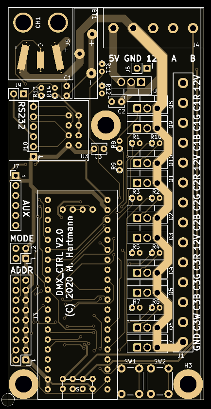
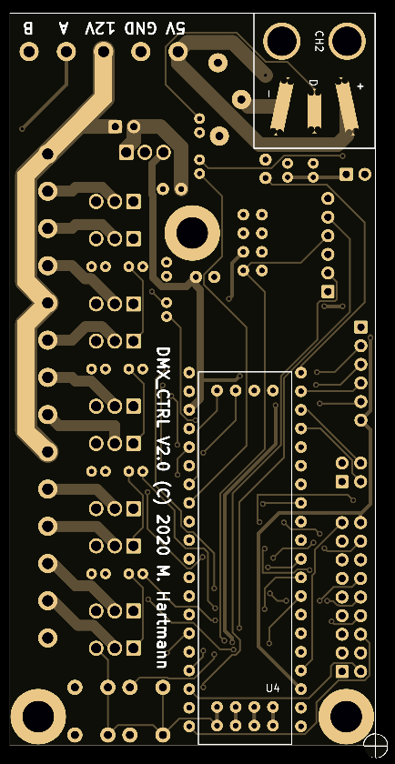
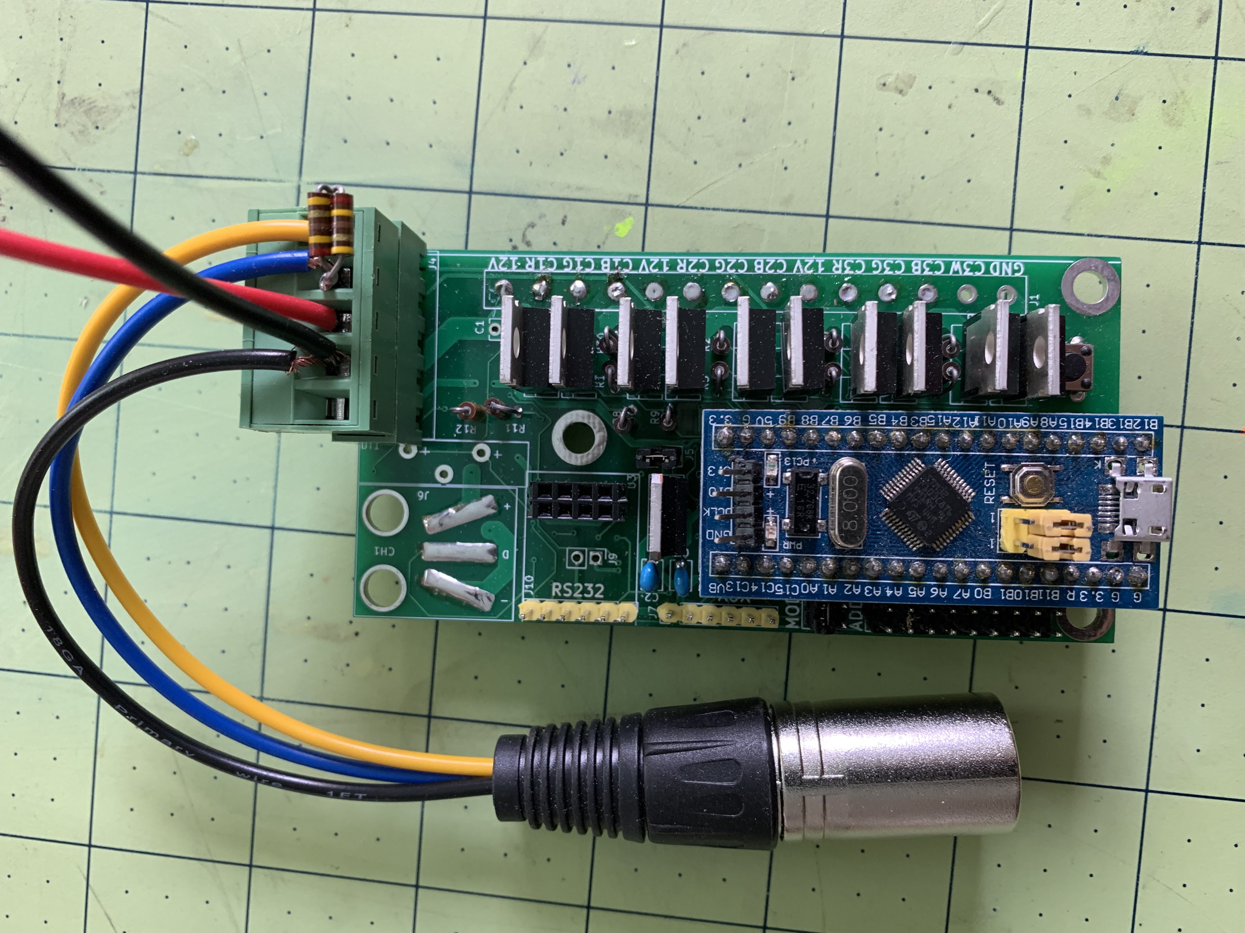
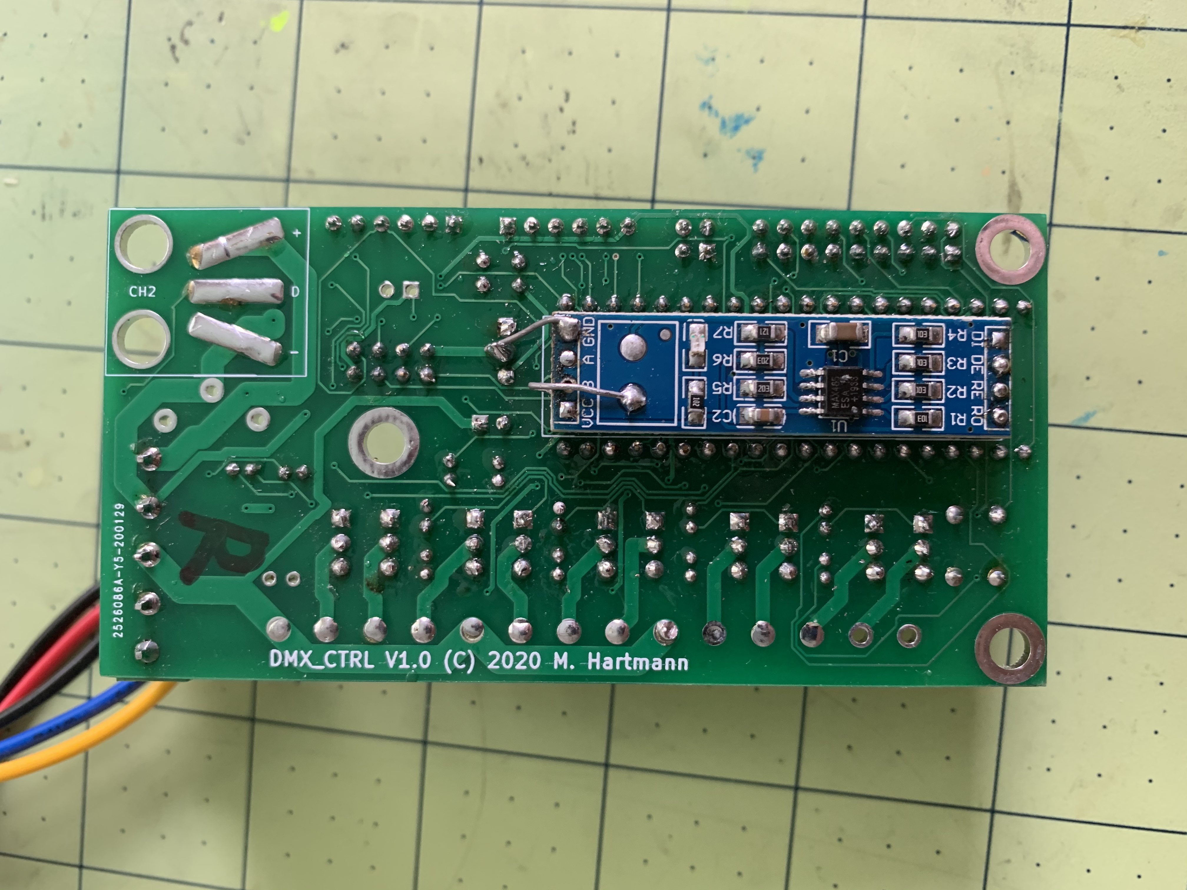
The BOM cost for the simplest implementation is
The software is developed with ST Microelectronics STM32CubeIDE 1.3.0 The software framework was generated with STM's ST CubeMX Solution (Config file included in DOC folder) and uses ST's HAL framework. (Not my favorite but that's what they want you to use...) I use a ST-Link V2.0 Clone to upload/Debug software. (Eventually there might be a USB DFU Firmware Upload Client....)
You can also use MS Visual Studio Code + PlatformIO. This is prefered if you run into issues with fake STM32's as PlatformIO uses openOCD which can set the device ID directly and program these devices. There are currently a lot of bluepill STM32F103 board clones with fake STM32F103 circulating on Amazon. (I ended up with about 20...Aarrggghhh...) As a workaround, you can edit the file ~/.platformio/packages/tool-openocd/scripts/target/stm32f1x.cfg and change the line: set _CPUTAPID 0x1ba01477 to: set _CPUTAPID 0x2ba01477
USB does not seem to work on my clones but I need to further test that....(I had issues like that before and usually it had to do with crappy USB cables...)
Here is another description how to fix it in STM32CubeIDE for openOCD debugging: https://community.st.com/s/question/0D50X0000BTd7Zi/how-to-deal-wirh-could-not-verify-st-device-
Update: Not all fake chips have 128 kB, some only have 64 kB. At that point the FW can not write the configruation to page 127... This will cause a Hardware Fault. Change the EEPROM page in eeprom.h from 127 to 63 and modifiy the .id file to reflect the smaller FLASH size. (Less effects will obviously fit in there....) I should probably figure out a way to detect flashsize automatically.....
Depending on mode selection the module will present itself with either 11 or 26 DMX Registers. In Mode 1 only the first 11 registers are available and provide simple PwM control.
In Mode 2 additional 15 registers are present for FX control. (WS2812B supporty will only be present in that mode...) Except for the FX_SELECT register these don't do anything by default but have to be used in plugins. and functionality will vary.
The 8 Address Jumpers set the DMX Start address for the Registers. As there are 512 possible DMX Addresses the Address set via jumpers will be multiplied by 2.
Jumper 1 Disabled = DMX Register Mode 1 (Only PWM Control, not FX) Enabled = DMX Register Mode 2 (PWM + WS2812B Strips, FX enabled
In DMX Mode 1 only the following Registers will be available: #define MAX_BRIGHTNESS 0 #define CH1_RED 1 #define CH1_GREEN 2 #define CH1_BLUE 3 #define CH2_RED 4 #define CH2_GREEN 5 #define CH2_BLUE 6 #define CH3_RED 7 #define CH3_GREEN 8 #define CH3_BLUE 9 #define CH3_WHITE 10
In DMX Mode 2 additionally the following Registers will be available: #define FX_SELECT 11 #define STRIP1_PATTERN 12 #define STRIP1_SPEED 13 #define STRIP1_SIZE 14 #define STRIP1_COMPLEXITY 15 #define STRIP1_V1 16 #define STRIP1_V2 17 #define STRIP1_V3 18 #define STRIP2_PATTERN 19 #define STRIP2_SPEED 20 #define STRIP2_SIZE 21 #define STRIP2_COMPLEXITY 22 #define STRIP2_V1 23 #define STRIP2_V2 24 #define STRIP2_V3 25
Jumper 2 Disabled = No USB Support (Saves a lot of memory) Enabled = Enables Serial Port via USB
With my controller the follwing pinout works (Looking at a male connector): Pin 1 = GND Pin 2 = A Pin 3 = B Some controllers allow to swap A/B with a switch so your milage might vary....
DMX needs to be terminated at the end of the chain with a 160 Ohm Resistor.
Board has been tested with 9 PWM channels with 216 RGB LED's with a total power consumption of 3.8A @ 12V. If only 12V is supplied make sure to add J5 so the microcontroller is powered.
Pressing the button while powering up will erease all settings and restore the defaults.
Pressing the button after powering up will turn on test mode where the module cycles through all lights to test wiring
The two trigger inputs can be set up in different ways:
The analog value (0...3.3V) is directly mapped onto one of the control registers. (For example an external inpout can be linked to the brightness of a channel or set the input parameter for an effect)
A Specific value can be written to a specific control register wen crossing a threshold from low to high or from high to low. (For example a specific effect can be turned on/off via a switch)
USB Support can be complelty commented out in main.h as it saves a lot of RAM/Flash. If USB Support is compiled in Mode Jumper 1 controls if it is eanbled or not. USB has been confirmed working both witrh original STM32103F and STM clones but it is imperative to use good USB cables. Also be aware that some boards will need R10 on the bluepill boards swapped from 10kOhm to 1.5kOhm. Both the Shell or the Serial DMX protocol can be run via USB. On Win10 no special driver is needed, the device will be recognizied as a Serial port. The serial port emulation via USB is not speed-controlled so in theory data can be written at full 12Mbit/sec Full USB speed....
[TBD, Protocol Implemented, need sample App..] [TBD, need ESP2866 Sample Code and Sample App]
TBD
The LED strips seem to be very sensitive regarding the voltage on the data line. R11/R12 in theory protect the first LED from dying on transient overcurrent on startup but some LED strips won't work. In that case just bridge R11/R12....
The idea is to solder on wires and then use a zip-tie through the holes and hot-glue to secure the wires. Past projects had big problems with wires breaking off or shortening out... Maybe this will work.....
Example Code to use WS2812B on STM32 with DMA https://michaeltien8901.github.io/stm32/2018/07/19/Using-STM32-SPI-For-LED-STRIP.html
DMX512 Example https://github.com/carl3721/stm32-dmx512
DMX Pinout https://interactive-online.com/resources/faq/dmx-512-connector-pinouts
Fadecandy Webpage https://github.com/scanlime/fadecandy
Ultra-Cheap DMX Lights (Just search for DMX512 RGB LED on ebay...)
Bluepill Boards https://stm32-base.org/boards/STM32F103C8T6-Blue-Pill.html
(These can obviouslty be sourced way cheaper on ebay/alibaba/banggood... These links are just for reference...)
Run data as fast as possible via USB to 2 WS2812B strips. (512 LED * 30 us) + 60 us = 15.4 ms (64 FPS) 512 Leds = (512 * 3) * 1.2 bytes = 1843 Bytes
1843 Bytesa * 64 Frames = 117964 Bytes 117964 Bytes * 2 = 235929 Bytes = 1887436 Bits 12 MBits = 12000000 Bits 12000000 Bits / 1887436 = 6.35 So in theory we have 6.35x the bandwidth we need to update 2x 512 LED's 64 Times/sec....
| Qty | Value | Footprint | References |
|---|---|---|---|
| 12 | 1K | Resistor_THT:R_Axial_DIN0204_L3.6mm_D1.6mm_P1.90mm_Vertical | R1, R2, R3, R4, R5, R6, R7, R8, R9, R10, R13, R14 |
| 10 | IXTP3N50D2 | Package_TO_SOT_THT:TO-220-3_Vertical | Q1, Q2, Q3, Q4, Q5, Q6, Q7, Q8, Q9, Q10 |
| 3 | MountingHole | MountingHole:MountingHole_4.3mm_M4_DIN965_Pad | H1, H2, H3 |
| 2 | 330 | Resistor_THT:R_Axial_DIN0204_L3.6mm_D1.6mm_P1.90mm_Vertical | R11, R12 |
| 2 | SW_Push | Button_Switch_THT:SW_PUSH_6mm_H8mm | SW1, SW2 |
| 1 | 0.1uF | Capacitor_THT:C_Disc_D3.8mm_W2.6mm_P2.50mm | C3 |
| 1 | 0.22uF | Capacitor_THT:C_Disc_D3.8mm_W2.6mm_P2.50mm | C2 |
| 1 | 100nF | Capacitor_THT:C_Disc_D3.8mm_W2.6mm_P2.50mm | C1 |
| 1 | 12V Link | Connector_PinHeader_2.54mm:PinHeader_1x02_P2.54mm_Vertical | J5 |
| 1 | 3V3 UART | Connector_PinHeader_2.54mm:PinHeader_1x02_P2.54mm_Vertical | J9 |
| 1 | ADDR | Connector_PinHeader_2.54mm:PinHeader_2x09_P2.54mm_Vertical | J3 |
| 1 | AUX | Connector_PinHeader_2.54mm:PinHeader_1x06_P2.54mm_Vertical | J7 |
| 1 | Battery_Cell | DMX_PART_LIB:Vertical_3032_Coin_Batter_Holder | BT1 |
| 1 | ChinaBluePill | DMX_PART_LIB:ChinaBluePill | U1 |
| 1 | ESP-01 | DMX_PART_LIB:ESP-01 | U3 |
| 1 | LED_CONN | DMX_PART_LIB:LED_CONN_x14_5.08 | J1 |
| 1 | MODE | Connector_PinHeader_2.54mm:PinHeader_2x02_P2.54mm_Vertical | J2 |
| 1 | PWR | DMX_PART_LIB:PWR_CONN_x5_5.08 | J4 |
| 1 | RS485_Transeiver | DMX_PART_LIB:RS485_Transeiver | U4 |
| 1 | TTL_UART | Connector_PinHeader_2.54mm:PinHeader_1x06_P2.54mm_Vertical | J10 |
| 1 | WS2812_Conn | DMX_PART_LIB:WS2812_Dual_SMD | J6 |
| 1 | uA7805 | Package_TO_SOT_THT:TO-220-3_Vertical | U2 |
It measures 50 × 100 mm and has 2 copper layers, 1.6 mm thick.
46 parts, built around the ESP-01 and IXTP3N50D2. The full list of its parts is on this page, with links to each part's symbol and footprint where PCBKit's library has them.
From the michar71/DMX_CTRL repository on GitHub, at the commit this page was made from: the board is HW/DMX_CTRL/DMX_CTRL.kicad_pcb. PCBKit opens the board in the browser, with nothing to install.
Its repository states no licence, so its author keeps all rights: ask michar71 before reusing the design.
UzixLS/mist1010-board
10x10cm PCB variant of MIST FPGA project for G738/G706 enclosure


Rangarig/MK312WIFI
A replacement for the MK312's bluetooth adapter that allows to connect to it via wifi ... or comport

slemanz/chronolog
STM32-based temperature data logger with RTC, NOR flash storage, LCD and Wi-Fi. Hardware and firmware.

beckdac/uArm-MicroView-esp8266
uArm control PCB with MicroView (Arduino w/ OLED) and esp8266 WiFi/UART bridge


ArtoLabs/Sensi-pot
Collection of modules for indoor/outdoor gardening automation and environmental control
