4 layers29 × 50.3 mm
Lg hvac esp32
JanM321/esphome-lg-controller
Wired controller for LG HVAC units using ESPHome and ESP32
15 parts2920BSD
 dhzh-eph/PCBSensor
Devices are also often designed as Master-Slave architecture, the Master often as a microcontroller like an ESP32 or an Arduino in this case.
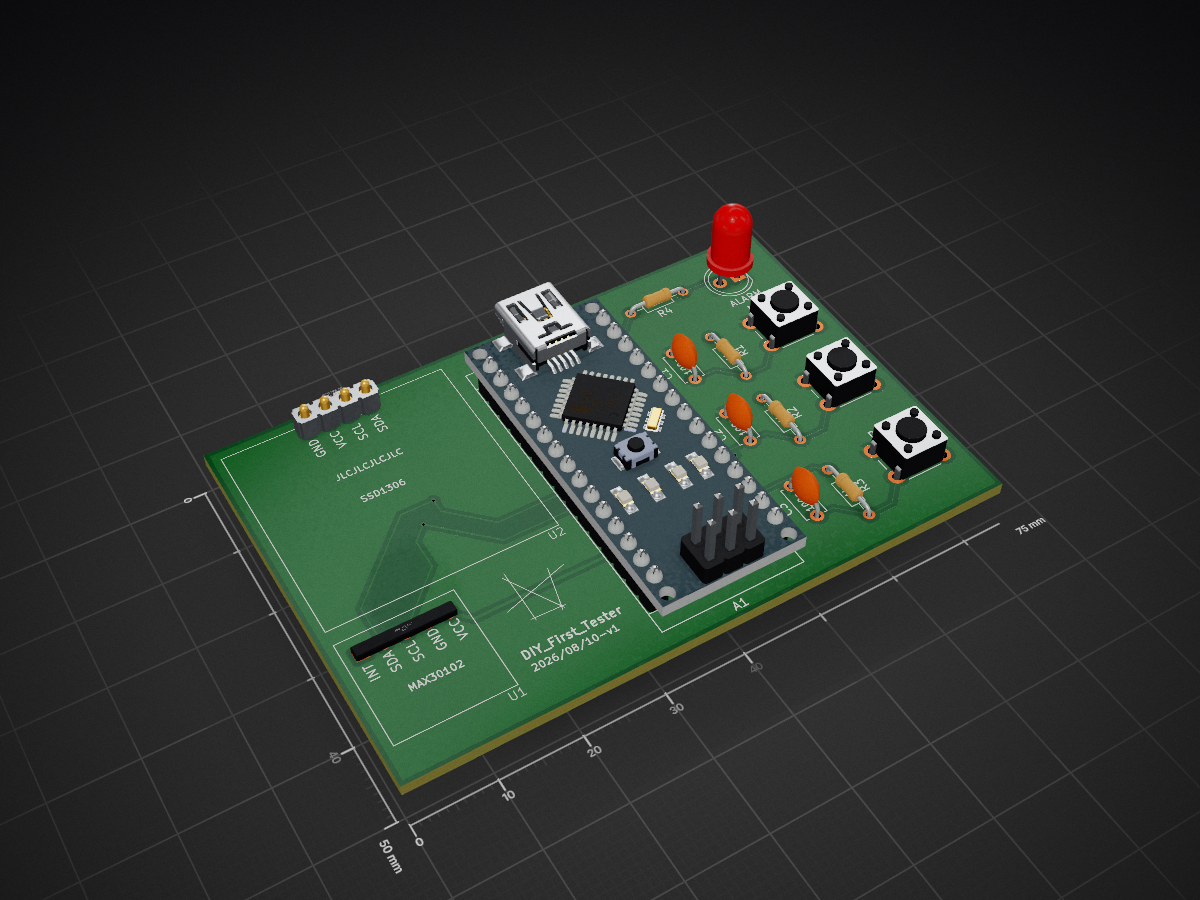
PCBtutorial is an open-source printed circuit board by dhzh-eph, from the dhzh-eph/PCBSensor repository on GitHub. It is a 4-layer board of 75 × 50 mm with 15 parts on 31 nets, routed with 58 tracks and 4 vias.
Its parts include 4 resistors, 3 capacitors and 2 ICs. It belongs with the lEDs and displays boards and the AVR (ATmega, ATtiny) boards of this library.
The MAX30102 is an integrated pulse oximetry (checks for oxygen levels) and heart rate monitor, often used in wearable electronics and fitness trackers. The sensor works through shining infrared LED and red LED into the skin, and a photodetector measures the amount of light reflected. This works because blood flow changes with every heartbeat, and in this case would absorb different amounts of light depending on oxygen, and the sensor can hence calculate heart rate and blood oxygen levels.
The SSD1306 is a OLED display, mainly used to display information to the user when communicating with the interface. It communicates using the I2C protocol, which means only 4 connections are needed, generally as GND, VCC or VDD, SCL, and SDA. The one being used is 128x64.
GND is the reference point for the vast majority of circuits and electronic designs, often as 0V. This is generally to keep circuits consistent and prevent uneven voltage points throughout circuit designs. VCC is generally the voltage potential of a source, often a battery of sorts. SCL is serial clock line, which mainly works as a clock or pulse in sending signals. Lastly, SDA is serial data access, which carries data bits.
I2C also known as Inter-Integrated Circuit, is a communication protocol used for microcontrollers to sensors, displays and other peripheral devices. In particular, I2C uses just two wires for data transfer between devices. These two wires are SDA and SCL, SDA transmits data back and forth and SCL is the clock signal from the master device to synchronize data transmission.
Devices are also often designed as Master-Slave architecture, the Master often as a microcontroller like an ESP32 or an Arduino in this case. The slave is the peripheral devices, like temperature sensors or OLED displays that listen for their address and act accordingly. Slave devices each have unique addressing, so one master can control multiple peripheral devices. Data is also sent one bit after another, synchronized accordingly to the clock pulses by the master.
Here is the image of the PCB on KiCad.
Here as such, is the wiring of the PCB. It is quite straightforward, mainly having the Arduino Nano power the other two embedded devices, and connected to their four core terminals.
Using this as reference for Arduino Code https://lastminuteengineers.com/arduino-nano-pinout/ we can then code for communication to the other two embedded systems. One thing to note is that the Arduino Nano being used here only works with ATega328P (Old Bootloader). This depends on whether the Arduino Nano's being used are older and cheaper or newer.
One thing to note is that a data transfer USB cable is required. Regular DC USB's for charging phones and such do not work for arduino nano.
sources
https://www.youtube.com/@HTMWorkshop <-- PCB design
https://www.youtube.com/watch?v=V5UvNVQsUsY <-- explanation for MAX30102
https://www.youtube.com/watch?v=8AvvRYcrOrE <-- explanation for SSD1306
good to know
https://www.youtube.com/watch?v=ICXznCN3NOI <-- sources for I2C and SPI
| Qty | Value | Footprint | References |
|---|---|---|---|
| 4 | 1k | Resistor_THT:R_Axial_DIN0204_L3.6mm_D1.6mm_P7.62mm_Horizontal | R1, R2, R3, R4 |
| 3 | 100n | Capacitor_THT:C_Disc_D4.7mm_W2.5mm_P5.00mm | C1, C2, C3 |
| 3 | SW_Push | Button_Switch_THT:SW_PUSH_6mm | DOWN, MENU, UP |
| 1 | Arduino_Nano_v3.x | Module:Arduino_Nano | A1 |
| 1 | LED | LED_THT:LED_D5.0mm | ALARM |
| 1 | LOGO | LOGO | G*** |
| 1 | MAX_Module | FootLibTut:Max_MODULE | U1 |
| 1 | SDDTester | FootLibTut:SSD | U2 |
It measures 75 × 50 mm and has 4 copper layers, 1.6 mm thick.
15 parts. The full list of its parts is on this page, with links to each part's symbol and footprint where PCBKit's library has them.
From the dhzh-eph/PCBSensor repository on GitHub, at the commit this page was made from: the board is PCBtutorial/PCBtutorial.kicad_pcb and its schematic PCBtutorial/PCBtutorial.kicad_sch. PCBKit opens the board in the browser, with nothing to install.
Its repository states no licence, so its author keeps all rights: ask dhzh-eph before reusing the design.
JanM321/esphome-lg-controller
Wired controller for LG HVAC units using ESPHome and ESP32


niklasekstrom/clockport_pi_interface
Amiga clock port to Raspberry Pi interface

RoboticsBrno/RB0005-UniversalStepDown
Universal step-down module

OpenDevicePartnership/pico-de-gallo
A tool for testing Embedded Rust drivers for discrete I2C/SPI components.
