2 layers28.3 × 39.8 mm
LevelShifter
gusmanb/logicanalyzer
24 channel, 100Msps logic analyzer hardware and software
21 parts5.1kGPL-3.0

 dhanupragateesh26/AERO_linefollower1
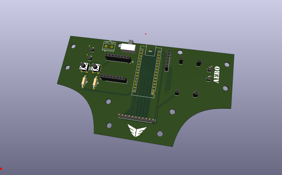
Aero pcblayout is an open-source printed circuit board by dhanupragateesh26, from the dhanupragateesh26/AERO_linefollower repository on GitHub, published under the MIT licence. It is a 2-layer board of 140 × 80 mm with 21 parts on 40 nets, routed with 176 tracks and 2 vias.
Its parts include 13 connectors, 3 switches and 2 resistors. It belongs with the AVR (ATmega, ATtiny) boards of this library.
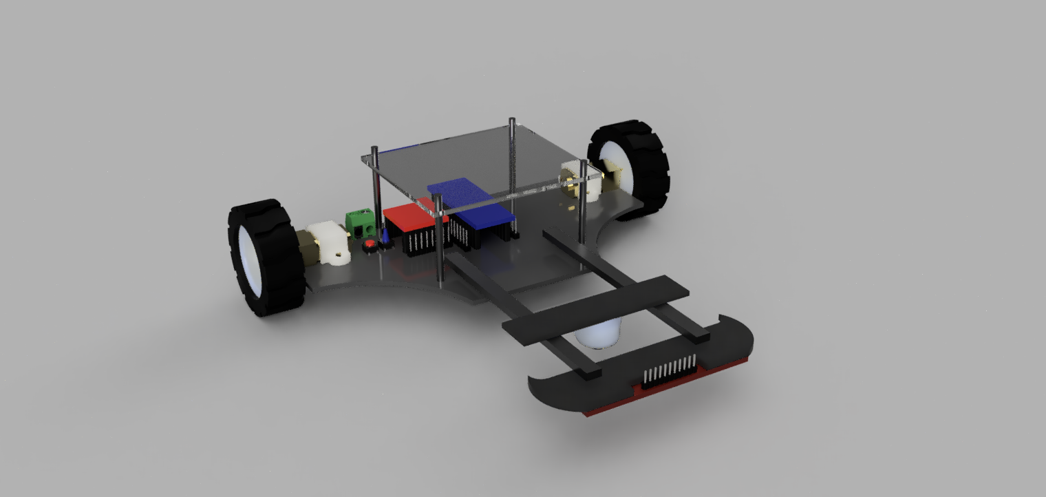
AERO is an autonomous line follower bot designed to detect and follow a path using IR sensors and motor control logic. It features an open-source hardware design with schematics and PCB layout, making it ideal for learning robotics, embedded systems, and circuit design.
| Component | Quantity | Description |
|---|---|---|
| Arduino Nano/ | 1 | Microcontroller board |
| QTR8RC | 1 | 8 channel IR array |
| TB6612FNG Motor Driver | 1 | Dual H-bridge for DC motors |
| N20 Motors + Wheels | 2 | Robot locomotion |
| 12V Li-Po | 1 | Li-polymer battery |
| Custom PCB | 1 | Hand Soldered |
| Chassis | 1 | 3-D printed |
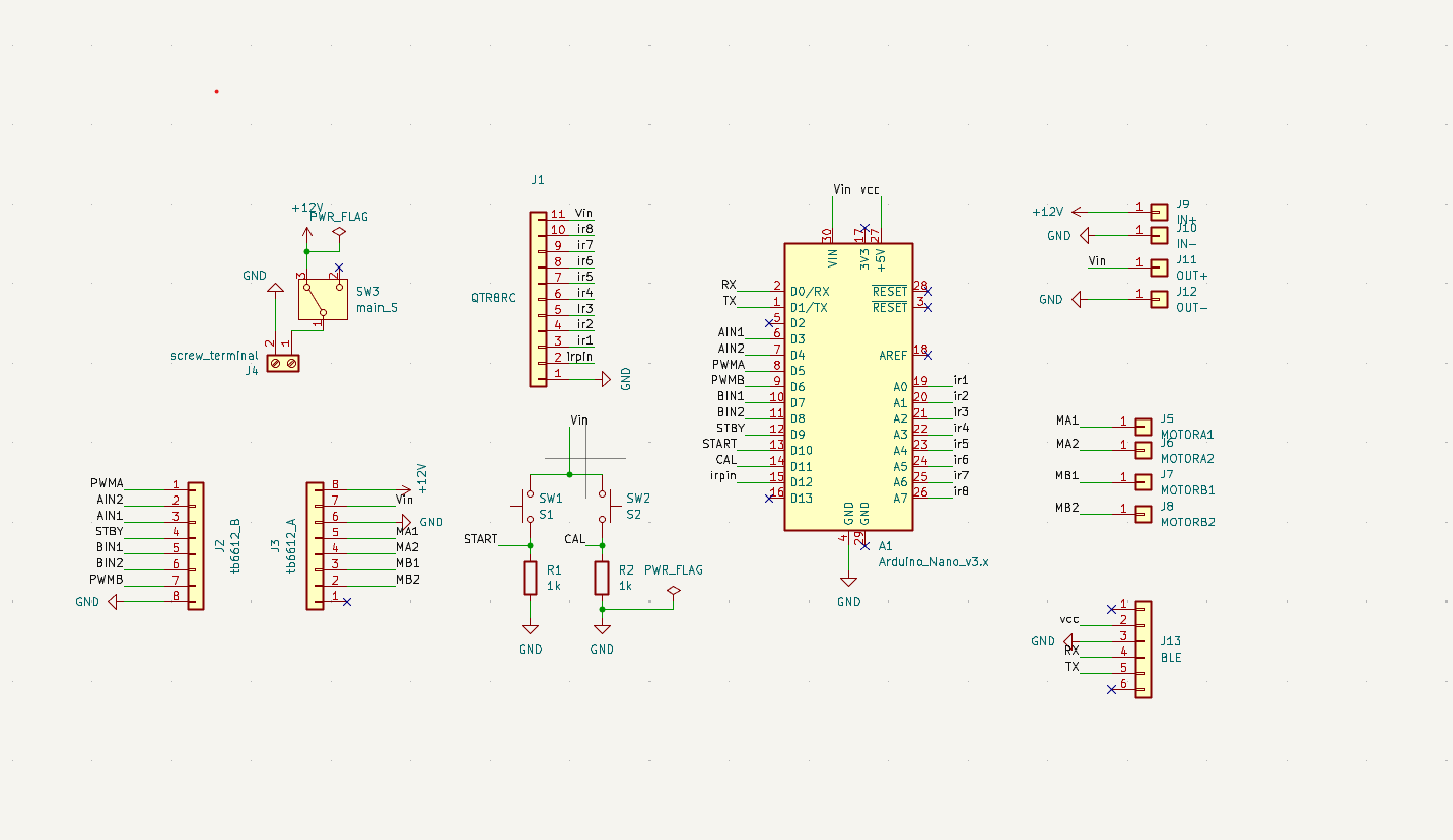
| Qty | Value | Footprint | References |
|---|---|---|---|
| 2 | 1k | Resistor_THT:R_Axial_DIN0207_L6.3mm_D2.5mm_P10.16mm_Horizontal | R1, R2 |
| 1 | Arduino_Nano_v3.x | Module:Arduino_Nano | A1 |
| 1 | BLE | Connector_PinSocket_2.54mm:PinSocket_1x06_P2.54mm_Vertical | J13 |
| 1 | IN+ | Connector_PinSocket_2.54mm:PinSocket_1x01_P2.54mm_Vertical | J9 |
| 1 | IN- | Connector_PinSocket_2.54mm:PinSocket_1x01_P2.54mm_Vertical | J10 |
| 1 | LOGO | LOGO | G*** |
| 1 | MOTORA1 | Connector_PinHeader_2.54mm:PinHeader_1x01_P2.54mm_Vertical | J5 |
| 1 | MOTORA2 | Connector_PinHeader_2.54mm:PinHeader_1x01_P2.54mm_Vertical | J6 |
| 1 | MOTORB1 | Connector_PinHeader_2.54mm:PinHeader_1x01_P2.54mm_Vertical | J7 |
| 1 | MOTORB2 | Connector_PinHeader_2.54mm:PinHeader_1x01_P2.54mm_Vertical | J8 |
| 1 | OUT+ | Connector_PinSocket_2.54mm:PinSocket_1x01_P2.54mm_Vertical | J11 |
| 1 | OUT- | Connector_PinSocket_2.54mm:PinSocket_1x01_P2.54mm_Vertical | J12 |
| 1 | QTR8RC | Connector_PinHeader_2.54mm:PinHeader_1x11_P2.54mm_Vertical | J1 |
| 1 | S1 | Button_Switch_THT:SW_PUSH_6mm_H7.3mm | SW1 |
| 1 | S2 | Button_Switch_THT:SW_PUSH_6mm_H7.3mm | SW2 |
| 1 | main_S | Button_Switch_THT:SW_Slide-03_Wuerth-WS-SLTV_10x2.5x6.4_P2.54mm | SW3 |
| 1 | screw_terminal | TerminalBlock_RND:TerminalBlock_RND_205-00232_1x02_P5.08mm_Horizontal | J4 |
| 1 | tb6612_A | Connector_PinSocket_2.54mm:PinSocket_1x08_P2.54mm_Vertical | J3 |
| 1 | tb6612_B | Connector_PinSocket_2.54mm:PinSocket_1x08_P2.54mm_Vertical | J2 |
The 20 most common of 21 parts.
It measures 140 × 80 mm and has 2 copper layers, 1.6 mm thick.
21 parts. The full list of its parts is on this page, with links to each part's symbol and footprint where PCBKit's library has them.
From the dhanupragateesh26/AERO_linefollower repository on GitHub, at the commit this page was made from: the board is Aero_pcblayout.kicad_pcb and its schematic Aero_schematic.kicad_sch. PCBKit opens the board in the browser, with nothing to install.
Its repository publishes it under the MIT licence: you may reuse it on that licence's terms (keep the author's notice, and for a copyleft licence share your changes alike).
gusmanb/logicanalyzer
24 channel, 100Msps logic analyzer hardware and software

mntmn/amiga2000-gfxcard
MNT VA2000, an Open Source Amiga 2/3/4000 Graphics Card (Zorro II/III), written in Verilog


hackclub/OnBoard
💡 Join 1,000 teenagers and make your first PCB with a $100 grant!

drandyhaas/KiCadRoutingTools
A set of Python/Rust tools to aid routing in KiCad

Arrow-air/project-quiver
Project Quiver documentation, designs, and project artifacts.

