


2 layers45 × 35 mm
I2c sensor
devkyber/PCB
AI-assisted PCB engineering for native KiCad: source evidence, scoped changes, checked previews, human review, and reproducible release packages.
17 parts
 devkyber/PCB
AI-assisted PCB engineering for native KiCad: source evidence, scoped changes, checked previews, human review, and reproducible release packages.
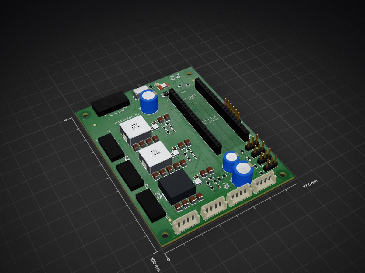
Rover pdb is an open-source printed circuit board by devkyber, from the devkyber/PCB repository on GitHub. It is a 2-layer board of 77.5 × 100 mm with 93 parts on 69 nets, routed with 449 tracks and 168 vias.
It is built around the INA226AIDGSR, CL32B226KAJNNNE and CL21B104KBCNNNC, with the RC0805FR-0710KL, EEU-FR1H221B and CSS2H-2512K-2L00F among its other parts. Its parts include 32 capacitors, 21 resistors, 13 connectors, 4 ICs and 3 inductors. It belongs with the robots and motor control boards and the RP2040 boards of this library.


An unbuilt educational DRAFT for trying PCB Copilot on a complete, small KiCad design. Four independent 0 to 3.3 V inputs drive four red LEDs through 1.1 kOhm resistors. The 45 x 35 mm board has two copper layers, through-hole components, two mounting holes, project-local libraries and all three package models.
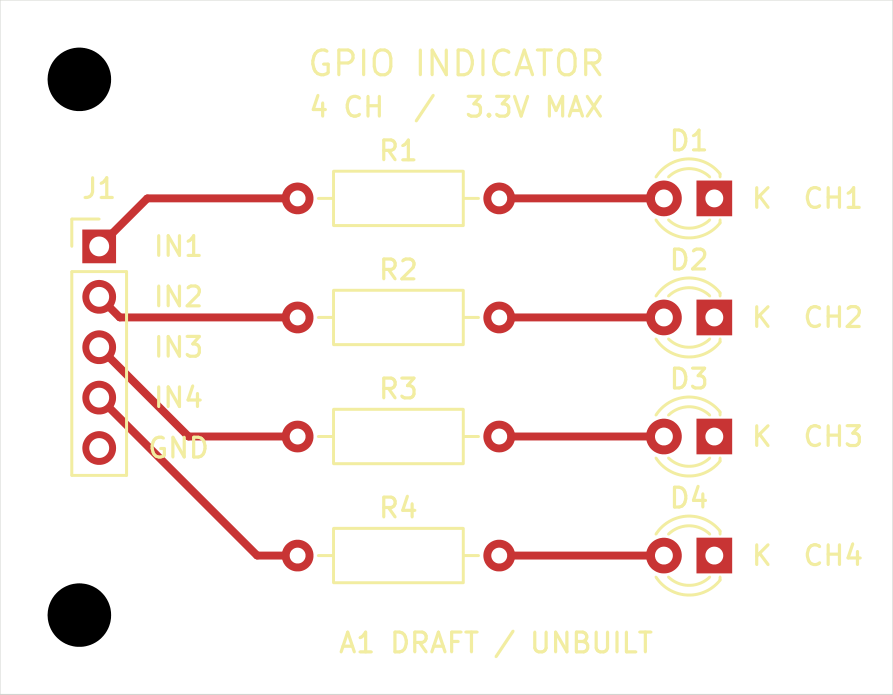
Open gpio-indicator.kicad_pro in KiCad 10, or inspect the schematic PDF, schematic image, assembly drawing, front copper and mirrored underside. The GLB model is a native CAD visualization; it does not establish actual component fit.
From the repository root:
uv run pcb-copilot doctor
uv run pcb-copilot status examples/gpio-indicator
uv run pcb-copilot research examples/gpio-indicator --verify
uv run pcb-copilot research examples/gpio-indicator --verify-schematic-parts
uv run pcb-copilot review examples/gpio-indicator
The last command deliberately returns exit 1: supplier assembly rotation contracts and all five human review decisions are absent. Native ERC and DRC are clean, connectivity and forward-annotation links agree, and the independent dated JLCPCB geometry check passes. These results are scoped machine checks, not fabrication approval or measured performance. See the saved review and author inspection record.
J1 pins 1 through 4 are IN1 through IN4; pin 5 is GND. It has no power pin. With a 3.3 V input and initial 1% resistance tolerance, the calculation gives at most 3.031 mA per channel, taking no credit for LED forward voltage. That loading must suit the actual controller's per-pin and aggregate drive limits. Actual brightness, current, fit, assembly and external-controller behavior remain unqualified.
The resistor was deliberately chosen as 1.1 kOhm: 1 kOhm at its negative 1% tolerance would allow a 3.333 mA zero-Vf bound. The requirements and design basis state the assumptions and scope. This example has no ESD protection, isolation, level conversion, voltage regulation or approval for an application.
Exact manufacturer PDF bytes are in evidence. The library receipt binds official KiCad footprint copies, pad functions, manufacturer evidence and local model bytes to their hashes. The local footprint files change only model URIs. Board instances use wider silkscreen strokes to meet the workspace baseline; numbered pad geometry is unchanged. Generic package models are visualization aids.
The saved native CAD is authoritative. A construction script must not overwrite later edits. Use a separate copy for experiments and the shared candidate workflow for checked updates. No owner board or frozen test fixture was modified to create this example.
| Qty | Value | Footprint | References |
|---|---|---|---|
| 10 | 10u / 50V | Capacitor_SMD:C_1210_3225Metric | C10, C11, C12, C13, C14, C15, C16, C17, C18, C19 |
| 9 | 22u / 25V | Capacitor_SMD:C_1210_3225Metric | C20, C21, C22, C23, C24, C25, C26, C27, C28 |
| 7 | 100k / 1% | Resistor_SMD:R_0805_2012Metric | R10, R11, R12, R13, R14, R15, R19 |
| 7 | 100n / 50V | Capacitor_SMD:C_0805_2012Metric | C3, C30, C31, C32, C33, C34, C35 |
| 4 | 10k | Resistor_SMD:R_0805_2012Metric | R3, R4, R5, R6 |
| 4 | MountingHole_3.2mm_M3 | MountingHole:MountingHole_3.2mm_M3 | H1, H2, H3, H4 |
| 3 | 1k / 1% | Resistor_SMD:R_0805_2012Metric | R21, R22, R23 |
| 3 | 33p / 50V | Capacitor_SMD:C_0603_1608Metric | C39, C40, C41 |
| 3 | AGND tie | rover:AGND_Tie_LMR51450 | NT1, NT2, NT3 |
| 3 | Fiducial | Fiducial:Fiducial_1mm_Mask2mm | FID1, FID2, FID3 |
| 3 | LMR51450SDRRR | rover:LMR51450_DRR_WSON12_3x3 | U2, U3, U4 |
| 2 | 220u / 50V | Capacitor_THT:CP_Radial_D10.0mm_P5.00mm | C1, C5 |
| 2 | 4k7 / 1% | Resistor_SMD:R_0805_2012Metric | R1, R2 |
| 1 | +12V | TestPoint:TestPoint_Pad_D2.0mm | TP3 |
| 1 | +3V3 | TestPoint:TestPoint_Pad_D2.0mm | TP5 |
| 1 | +5V | TestPoint:TestPoint_Pad_D2.0mm | TP4 |
| 1 | 12V EXP / UNWIRED | rover:WirePads_2_5x6_P9 | P3 |
| 1 | 19.1k / 1% | Resistor_SMD:R_0805_2012Metric | R16 |
| 1 | 22k / 1% | Resistor_SMD:R_0805_2012Metric | R24 |
| 1 | 2mR / 5W / 1% | rover:CSS2H_2512_6.35x3.05 | RS1 |
| 1 | 3.74k / 1% | Resistor_SMD:R_0805_2012Metric | R18 |
| 1 | 3k9 / 0.25W | Resistor_SMD:R_1206_3216Metric | R20 |
| 1 | 3u3 / APS1365DW | rover:APS1365DW_13.8x12.6_P11.5 | L3 |
| 1 | 470u / 16V | Capacitor_THT:CP_Radial_D8.0mm_P5.00mm | C2 |
| 1 | 4u7 / SRP1265A | rover:SRP1265A_LeadFrame_13.5x12.5_P11.1 | L2 |
| 1 | 5V EXP / UNWIRED | rover:WirePads_2_5x6_P9 | P4 |
| 1 | 6u8 / SRP1265A | rover:SRP1265A_LeadFrame_13.5x12.5_P11.1 | L1 |
| 1 | 7.15k / 1% | Resistor_SMD:R_0805_2012Metric | R17 |
| 1 | BATTERY IN | rover:WirePads_2_6x8_P12 | P1 |
| 1 | CAMERA PAN | Connector_PinHeader_2.54mm:PinHeader_1x03_P2.54mm_Vertical | J4 |
| 1 | EXP / DNP | Connector_PinHeader_2.54mm:PinHeader_1x06_P2.54mm_Vertical | J9 |
| 1 | GND | TestPoint:TestPoint_Pad_D2.0mm | TP6 |
| 1 | GREEN | rover:KT0805G_0805_A1_K2 | D2 |
| 1 | HAMMER | Connector_JST:JST_EH_B4B-EH-A_1x04_P2.50mm_Vertical | J7 |
| 1 | INA226AIDGSR | Package_SO:MSOP-10_3x3mm_P0.5mm | U1 |
| 1 | JETSON / BARREL | rover:WirePads_2_5x6_P9 | P2 |
| 1 | LEFT WHEELS | Connector_JST:JST_EH_B4B-EH-A_1x04_P2.50mm_Vertical | J5 |
| 1 | LIFT A | Connector_PinHeader_2.54mm:PinHeader_1x03_P2.54mm_Vertical | J2 |
| 1 | LIFT B | Connector_PinHeader_2.54mm:PinHeader_1x03_P2.54mm_Vertical | J3 |
| 1 | MOTOR ENABLE | Button_Switch_THT:SW_Slide_SPDT_Angled_CK_OS102011MA1Q | SW1 |
| 1 | Pico 2 / 2x20 sockets | rover:Pico2_Sockets_LXWCONN_254PM_1x20 | SKT1 |
| 1 | RIGHT WHEELS | Connector_JST:JST_EH_B4B-EH-A_1x04_P2.50mm_Vertical | J6 |
| 1 | SERVO AUX | Connector_PinHeader_2.54mm:PinHeader_1x03_P2.54mm_Vertical | J8 |
| 1 | U2D2 DATA IN | Connector_JST:JST_EH_B4B-EH-A_1x04_P2.50mm_Vertical | J1 |
| 1 | VBAT | TestPoint:TestPoint_Pad_D2.0mm | TP1 |
| 1 | VMOTOR | TestPoint:TestPoint_Pad_D2.0mm | TP2 |
devkyber/PCB
AI-assisted PCB engineering for native KiCad: source evidence, scoped changes, checked previews, human review, and reproducible release packages.

devkyber/PCB
AI-assisted PCB engineering for native KiCad: source evidence, scoped changes, checked previews, human review, and reproducible release packages.

devkyber/PCB
AI-assisted PCB engineering for native KiCad: source evidence, scoped changes, checked previews, human review, and reproducible release packages.

devkyber/PCB
AI-assisted PCB engineering for native KiCad: source evidence, scoped changes, checked previews, human review, and reproducible release packages.


DD1SB/ARDF-TX
Date: 2026-10-15. Engineering review only; unbuilt and unenergized. Open RF80.kicadpro, schematic and native PCB in KiCad10.0.6. Three primary PCBs and the separate VHF true-AM design are unchanged.


7757/fanduck
超能花钱鸭 Fanduck · Microduck 已复刻成功!分享实机演示、物料清单、3D 打印、板件、制作工具与 3D 镜像工作台。Build resources from our completed Microduck replica.

HeyPCB/hello-8051
HELLO: a tiny 8051 computer shaped like a 1984 desktop. AT89S52, 32 KB SRAM, 128x64 ST7920 LCD, USB-C. 112 x 158 mm 2-layer KiCad 10 board, DRC clean, firmware that writes hello. Built through HeyPCB's MCP server.


nathanfraske/CEC-Platform
ONE board file, kept current by the wave (owner directive 2026-07-25: "the current best should be placed into a candidate folder per board and kept current with only one board ideally so we have a reference").

It measures 77.5 × 100 mm and has 2 copper layers, 1.6 mm thick.
93 parts, built around the INA226AIDGSR, CL32B226KAJNNNE, CL21B104KBCNNNC and RC0805FR-0710KL. The full list of its parts is on this page, with links to each part's symbol and footprint where PCBKit's library has them.
From the devkyber/PCB repository on GitHub, at the commit this page was made from: the board is projects/rover-pdb/rover-pdb.kicad_pcb and its schematic examples/gpio-indicator/gpio-indicator.kicad_sch. PCBKit opens the board in the browser, with nothing to install.
Its repository states no licence, so its author keeps all rights: ask devkyber before reusing the design.