
2 layers60 × 30 mm
Controller
google/mozc-devices
Circuit diagrams and firmware source code for Gboard DIY keyboards
11 parts3kApache-2.0

ViniClock is an alarm clock to wake me up whenever I have to go to school; I don't want to miss the bus.
Blare is an open-source printed circuit board by Developer-Vini, from the Developer-Vini/Blare-ViniClock- repository on GitHub. It is a 2-layer board of 92.5 × 53.5 mm with 11 parts on 15 nets, routed with 72 tracks and 0 vias.
Its parts include 4 switches, 1 IC and 1 connector. It belongs with the lEDs and displays boards and the ESP32 and RISC-V boards of this library.
ViniClock is an alarm clock to wake me up whenever I have to go to school; I don't want to miss the bus.
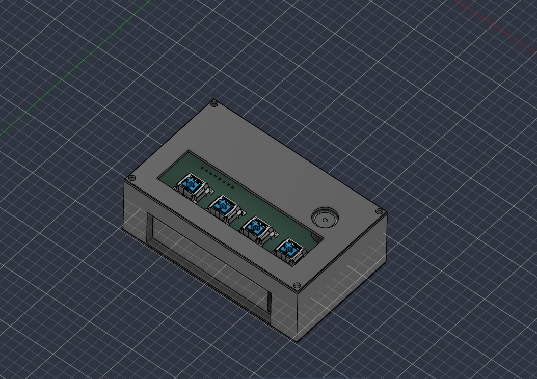
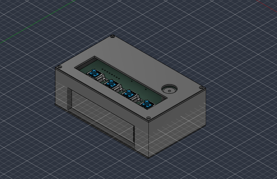
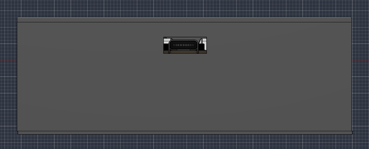
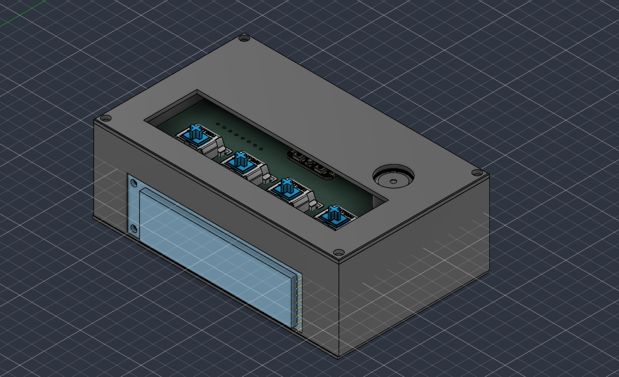
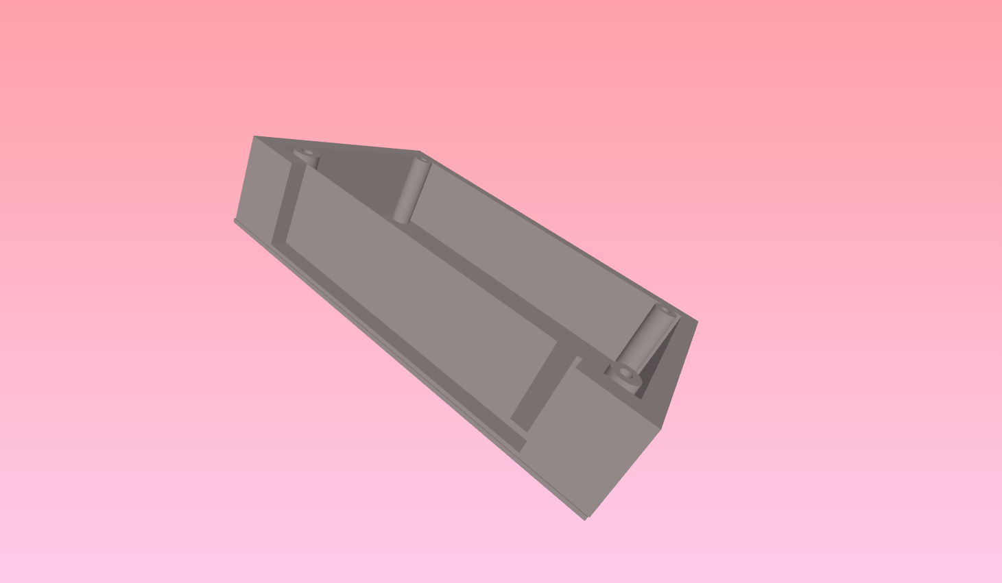
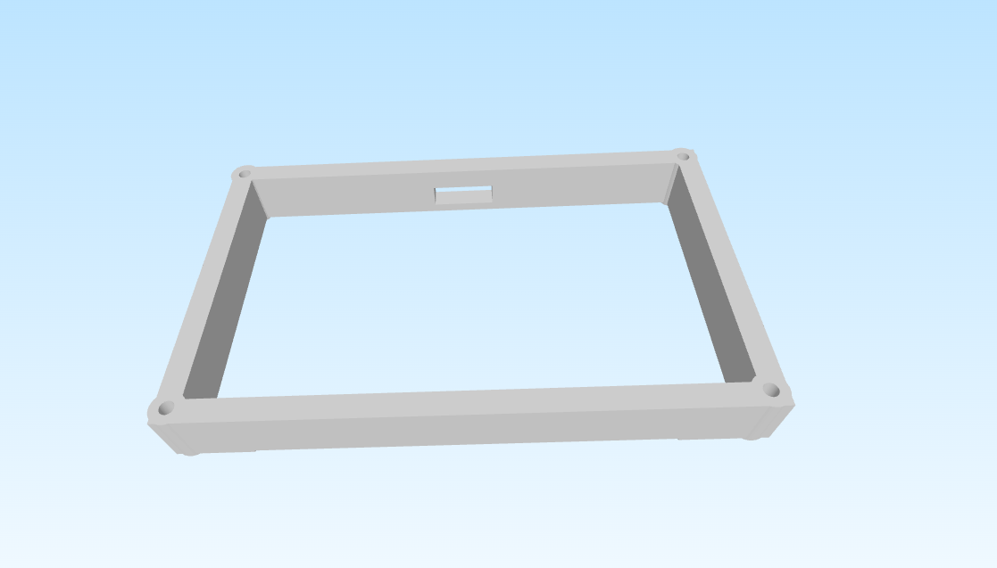
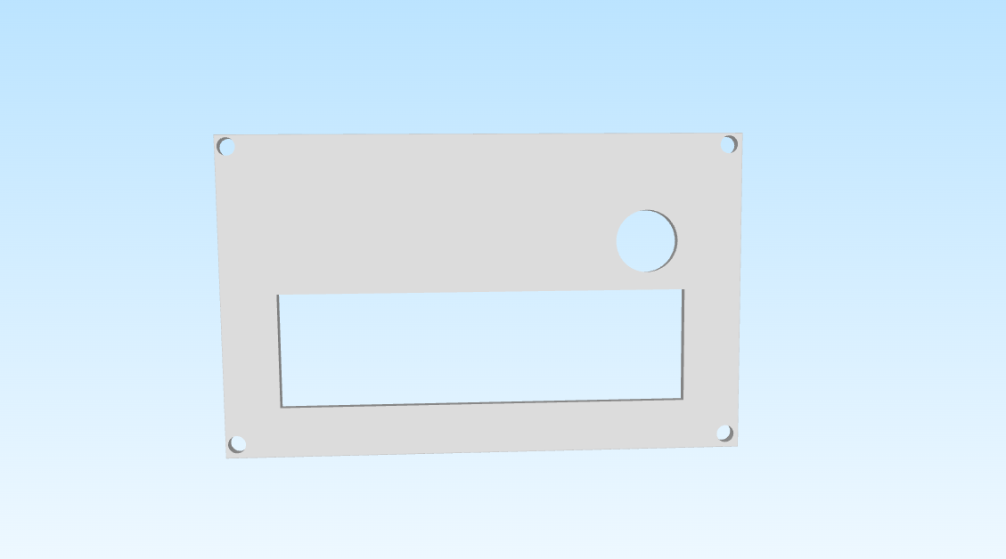
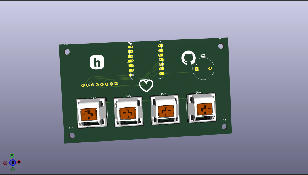
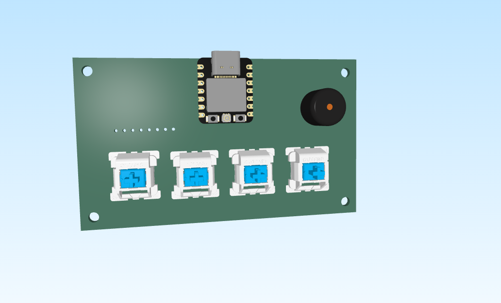
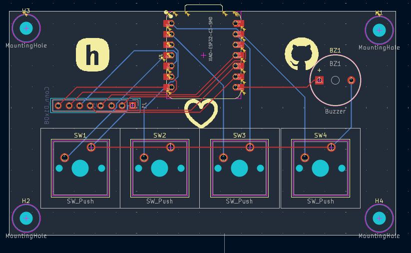
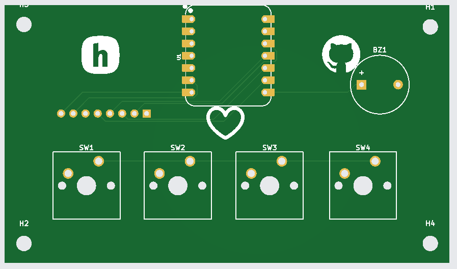
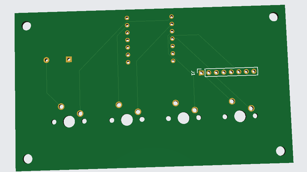
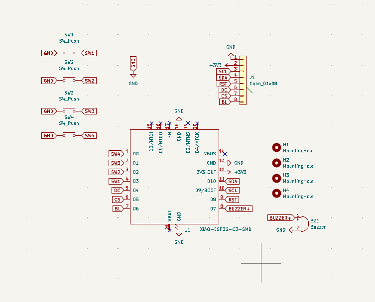
To view the diagram in more detail, download the PDF or open it right here on GitHub.
While developing the project, I learned various concepts and 3D modeling techniques; I learned to use Fusion 360 and how to work with sketches, extrusions, and much more. I also learned—or rather, improved upon—skills in KiCad that I hadn't mastered before. Moving forward, I plan to move away from using labels and instead try wiring things up to create a really neat, organized setup.
| Part | Description | Qty |
|---|---|---|
| BZ1 – Piezo Buzzer | Sound effects and audio feedback | 1 |
| J1 – Pin Header | 1×8 male header, 2.54 mm pitch | 1 |
| SW1–SW4 – Keyboard Switches | MX-style mechanical switches for user input | 4 |
| U1 – Seeed XIAO ESP32-C3 | Main microcontroller for device control | 1 |
| TFT Display | 2.25-inch display, 76 × 284 resolution | 1 |
| Keycaps | Blank white DSA keycaps, 1u size | 4 |
| Female-to-Female Jumper Wires | Wires for connecting the display to the PCB | 7 |
| M3 × 8 mm Screws | Screws for mounting the PCB | 4 |
| USB Charger | USB power adapter for powering the device | 1 |
| 3D-Printed Case | Custom enclosure to house and protect the electronics | 1 |
I’ll update the images later—I don’t have time right now—but I have updated the .step files; feel free to take a look.
The code was written entirely in C++—I personally prefer programming in C. It wasn't too hard to write, though I'm not sure if everything is 100% correct; I'll only know for sure once I get the kit and can test it, but my ego tells me it's spot on, haha. I could have tested it on Tinkercad, but it doesn't have the specific components I need.
There are also the notes; for now, I'm going to use the Nokia tune because I like it. I got the notes from this blog post: https://blog.eletrogate.com/relogio-despertador-arduino-com-melodia-personalizavel/ I was a bit short on ideas, so I might change it later—I think I'll create my own melody.
To run the project, you'll need to install the Arduino IDE—the tool used to upload (flash) the code to the Arduino. Once installed, connect the board to your PC using a USB-C cable (or another compatible one); the option to select the target board for flashing will appear in the top corner of the screen—just select it, and you're all set. Don't forget to clone the repo, then copy and open my code in the Arduino IDE.
For those of you who are too lazy to do the research yourself, here’s the link served up on a silver platter. https://support.arduino.cc/hc/en-us/articles/360019833020-Download-and-install-Arduino-IDE
Thanks! I'm going to add the timelapse of the README creation.
| Qty | Value | Footprint | References |
|---|---|---|---|
| 4 | MountingHole | MountingHole:MountingHole_3.2mm_M3 | H1, H2, H3, H4 |
| 4 | SW_Push | Button_Switch_Keyboard:SW_Cherry_MX_1.00u_PCB | SW1, SW2, SW3, SW4 |
| 1 | Buzzer | Buzzer_Beeper:Buzzer_12x9.5RM7.6 | BZ1 |
| 1 | Conn_01x08 | Connector_PinSocket_2.54mm:PinSocket_1x08_P2.54mm_Vertical | J1 |
| 1 | XIAO-ESP32-C3-SMD | Blare(ViniClock):XIAO-ESP32-C3-DIP | U1 |
It measures 92.5 × 53.5 mm and has 2 copper layers, 1.6 mm thick.
11 parts. The full list of its parts is on this page, with links to each part's symbol and footprint where PCBKit's library has them.
From the Developer-Vini/Blare-ViniClock- repository on GitHub, at the commit this page was made from: the board is PCB/blare.kicad_pcb and its schematic PCB/blare.kicad_sch. PCBKit opens the board in the browser, with nothing to install.
Its repository states no licence, so its author keeps all rights: ask Developer-Vini before reusing the design.
google/mozc-devices
Circuit diagrams and firmware source code for Gboard DIY keyboards


FrameworkComputer/ExpansionCards
Reference designs and documentation to create Expansion Cards for the Framework Laptop

hoglet67/RGBtoHDMI
Bare-metal Raspberry Pi project that provides pixel-perfect sampling of Retro Computer RGB/YUV video and conversion to HDMI

hackclub/OnBoard
💡 Join 1,000 teenagers and make your first PCB with a $100 grant!


tardate/LittleArduinoProjects
a collection of "Little Electronic & Arduino Projects", most involving electronics or an Arduino in one way or another!

basilfx/TRADFRI-Hacking
Hacking IKEA TRÅDFRI products, such as light bulbs, window blinds and other accessories.