2 layers56.1 × 37 mm
PowerBoard
dev-campusfab/chessLab
Interactive Chess board that brings visuals to the game and can help the player to learn.
44 parts2AGPL-3.0
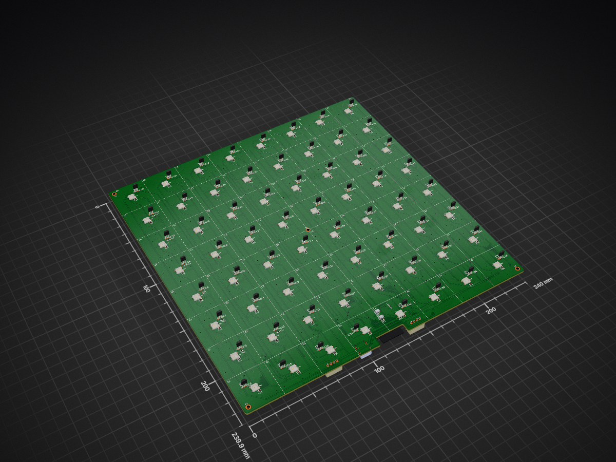
 dev-campusfab/chessLab2
Interactive Chess board that brings visuals to the game and can help the player to learn.
KiCad chessLab is an open-source printed circuit board by dev-campusfab, from the dev-campusfab/chessLab repository on GitHub, published under the AGPL-3.0 licence. It is a 2-layer board of 240 × 239.9 mm with 295 parts on 175 nets, routed with 2,221 tracks and 605 vias.
It is built around the ESP32-C6-WROOM-1-N8, SS49E and 74HC4051, with the 74HC138, WS2812B and TYPE-C-31-M-12 among its other parts. Its parts include 75 capacitors, 74 ICs, 72 resistors, 64 diodes and 3 connectors. It belongs with the ESP32 and RISC-V boards of this library.


Échiquier connecté détectant la position des pièces (capteurs à effet Hall) et affichant un retour visuel case par case (LEDs RGB adressables), pour visualiser une partie et aider à l'apprentissage du jeu.
                        ESP32-C6
        WiFi 6 · BLE 5 · RISC-V 160 MHz · 512 KB SRAM
                            |
        +-------------------+-------------------+
        |                   |                   |
  Capteurs Hall         LEDs RGB           Alimentation
(8x8 = 64) (8x8 = 64) Pack 18650Capteur à effet Hall Analogique, suffisant pour détecter la présence ou l'absence d'une pièce sur une case.
64 LEDs adressables individuellement, câblées en une seule chaîne série (une ligne de données, montage serpentin case par case). Alimentation 5 V, consommation crête d'environ 60 mA par LED.
64 capteurs analogiques dépassent le nombre de broches disponibles sur l'ESP32-C6. Solution retenue : multiplexeurs analogiques 74HC4051 (8 voies vers 1), soit 8 multiplexeurs pour 64 capteurs, ramenant le besoin à environ 11 broches ESP32.
Commutation assurée par un MOSFET P-Channel AO3401, piloté par le bouton d'alimentation et maintenu par l'ESP32 :
VBAT
 |
 R1 10k
 |
 +----------------------> Gate AO3401 (P-MOS)
 |                              |
 |        +---- R2 100k --------+
 |        |
 |     Source AO3401 = VBAT
 |        |
 |       Drain --------------------> VSYS
 |                                     |
BTN_PWR                          (MT3608 + AMS1117)
 |                                     |
 +---- vers Gate                 ESP32-C6
                                   |         |
                          GPIO_PWR_HOLD  GPIO_BTN_PWR
                          (maintien ON)  (lecture bouton)
Séquence d'allumage
Extinction logicielle
Extinction manuelle
| Carte principale | Carte d'alimentation |
|---|---|
| ESP32-C6 | TP4056 |
| Connecteur USB-C | DW01A + FS8205A |
| 64× WS2812B | Connecteur 18650 |
| 64× SS49E | MT3608 (5 V) |
| 8× 74HC4051 | AMS1117 (3,3 V) |
| 1× 74HC138 | Commutation MOSFET |
| BTN_BOOT + BTN_RESET | BTN_PWR + LED power |
| Connecteur JST vers carte d'alimentation | Connecteur JST vers carte principale |
Les deux cartes sont reliées par un connecteur JST 4 broches :
| Broche | Signal |
|---|---|
| 1 | VBAT (18650+) |
| 2 | GND |
| 3 | 5 V (sortie MT3608 vers carte principale) |
| 4 | 3,3 V (sortie AMS1117 vers carte principale) |
| Signal | Largeur |
|---|---|
| Données / GPIO | 0,25 mm |
| Alimentation 3,3 V | 0,5 mm |
| Alimentation 5 V (LEDs) | 1,0 mm |
| VBAT | 1,0 mm |
| VSYS | 1,0 mm |
| USB D+ / D- | 0,2 mm |
| Type | Perçage | Pad |
|---|---|---|
| Standard | 0,4 mm | 0,8 mm |
| Puissance | 0,6 mm | 1,2 mm |
| Broche | GPIO | Fonction |
|---|---|---|
| 13 | GPIO12 | USB D- |
| 14 | GPIO13 | USB D+ |
| 8 | GPIO0 | Mux — sélection canal S0 |
| 9 | GPIO1 | Mux — sélection canal S1 |
| 27 | GPIO2 | Mux — sélection canal S2 |
| 16 | GPIO18 | 74HC138 — sélection rangée A0 |
| 25 | GPIO16 | 74HC138 — sélection rangée A1 |
| 24 | GPIO17 | 74HC138 — sélection rangée A2 |
| 26 | GPIO3 | Lecture capteurs Hall (A_OUT) |
| 17 | GPIO19 | Données WS2812B (via résistance 33 Ω) |
| 18 | GPIO20 | VBAT |
| 15 | GPIO9 | Bouton BOOT |
| 19 | GPIO21 | Lecture bouton d'alimentation (BTN_PWR) |
| 20 | GPIO22 | Maintien alimentation (PWR_HOLD) |
Aimants cylindriques N52, Ø6×3 mm, insérés dans la base de chaque pièce et collés à l'époxy dans un logement imprimé en 3D. Ce choix permet une détection fiable par les capteurs Hall tout en restant invisible une fois la pièce posée.
Hauteur totale estimée : 25 à 30 mm, dimensionnée pour loger la carte principale, la carte d'alimentation et les deux packs 18650.
Architecture logicielle sous FreeRTOS, organisée en tâches indépendantes :
| Tâche | Rôle |
|---|---|
| Hall Scanner | Scrutation des 64 capteurs (polling 50 ms) |
| LED Controller | Traduction de l'état de l'échiquier en animation LED |
| Chess Engine | Validation des positions et des coups légaux |
| BLE/WiFi | Communication avec l'application mobile ou l'interface web |
| Battery Monitor | Suivi de la tension batterie via diviseur de tension sur ADC |
Bibliothèques envisagées
FastLED ou Adafruit NeoPixel pour le pilotage des WS2812BStockfish (version allégée, via WASM) pour le moteur d'échecs| Phase | Objectif |
|---|---|
| P1 | Prototype d'une case (1 LED + 1 capteur Hall + multiplexeur) sur breadboard |
| P2 | PCB de test 4×4 (KiCad) pour valider le multiplexage |
| P3 | PCB complet 8×8 et boîtier v1 |
| P4 | Firmware — moteur d'échecs et application |
| P5 | Impression 3D du boîtier final et des pièces modifiées |
| Qty | Value | Footprint | References |
|---|---|---|---|
| 73 | 100nF | Capacitor_SMD:C_0603_1608Metric_Pad1.08x0.95mm_HandSolder | C11, C12, C13, C14, C15, C16, C17, C18, C19, C20, C21, C22, C23, C24, C25, C26 +57 |
| 67 | 10k | Resistor_SMD:R_0603_1608Metric_Pad0.98x0.95mm_HandSolder | R13, R14, R15, R18, R19, R20, R21, R22, R23, R24, R25, R26, R27, R28, R29, R30 +51 |
| 64 | SS49E | chessLab-footprints:TO130P160X410X300-3P | IC10, IC11, IC12, IC13, IC14, IC15, IC16, IC17, IC18, IC19, IC20, IC21, IC22, IC23, IC24, IC25 +48 |
| 64 | WS2812B | chessLab-footprints:WS2812B | LED1, LED2, LED10, LED11, LED12, LED13, LED14, LED15, LED16, LED17, LED18, LED19, LED20, LED21, LED22, LED23 +48 |
| 8 | 74HC4051 | chessLab-footprints:74HC4051D653 | U4, U5, U6, U7, U8, U9, U10, U11 |
| 5 | MountingHole_Pad | MountingHole:MountingHole_2.2mm_M2_DIN965_Pad | H1, H2, H3, H4, H5 |
| 2 | 100k | Resistor_SMD:R_0603_1608Metric_Pad0.98x0.95mm_HandSolder | R16, R17 |
| 2 | 5.1k | Resistor_SMD:R_0603_1608Metric_Pad0.98x0.95mm_HandSolder | R10, R12 |
| 1 | 100uF | Capacitor_SMD:C_0603_1608Metric_Pad1.08x0.95mm_HandSolder | C9 |
| 1 | 10uF | Capacitor_SMD:C_0603_1608Metric_Pad1.08x0.95mm_HandSolder | C10 |
| 1 | 33 | Resistor_SMD:R_0603_1608Metric_Pad0.98x0.95mm_HandSolder | R11 |
| 1 | 74HC138 | Package_SO:SOIC-16_3.9x9.9mm_P1.27mm | U3 |
| 1 | BOOT | chessLab-footprints:B3U-1000P | SW3 |
| 1 | DATA | Connector_JST:JST_XH_B4B-XH-A_1x04_P2.50mm_Vertical | J5 |
| 1 | ESP32-C6-WROOM-1-N8 | chessLab-footprints:ESP32C6WROOM1N8 | IC4 |
| 1 | PWR | Connector_JST:JST_XH_B4B-XH-A_1x04_P2.50mm_Vertical | J6 |
| 1 | RST | chessLab-footprints:B3U-1000P | SW2 |
| 1 | TYPE-C-31-M-12 | chessLab-footprints:HRO_TYPE-C-31-M-12 | J4 |
dev-campusfab/chessLab
Interactive Chess board that brings visuals to the game and can help the player to learn.

frodegill/airsensor
PCB and Arduino code for custom air quality sensor


Mo-MoS/controllers
Controllers for MIDI, USB, Software Synths, VST Plugins.


jfm92/everAliveSensor
Solar-powered BLE environmental sensor (temp, humidity, pressure) with a 50F supercapacitor — potentially infinite lifetime, 19-day dark autonomy. ESP32 + BME680. Experimental.


RickKross/hector
Hector is a 38-key column staggered keyboard with HE magnetic sensors
It measures 240 × 239.9 mm and has 2 copper layers, 1.6 mm thick.
295 parts, built around the ESP32-C6-WROOM-1-N8, SS49E, 74HC4051 and 74HC138. The full list of its parts is on this page, with links to each part's symbol and footprint where PCBKit's library has them.
From the dev-campusfab/chessLab repository on GitHub, at the commit this page was made from: the board is Hardware/kiCad_chessLab/kiCad_chessLab.kicad_pcb and its schematic Hardware/kiCad_chessLab/cell.kicad_sch. PCBKit opens the board in the browser, with nothing to install.
Its repository publishes it under the AGPL-3.0 licence: you may reuse it on that licence's terms (keep the author's notice, and for a copyleft licence share your changes alike).