4 layers180 × 110 mm
PETER
dennowiggle/Retro-PETER
3.3V Retro computer project => FPGA + RCBUS + CPU boards making a custom system.
419 parts4LGPL-2.1

 dennowiggle/FLEADiP2
FLEADiP is a compatiable add-on board for the Z80 Retro! project
FLEADiP is an open-source printed circuit board by dennowiggle, from the dennowiggle/FLEADiP repository on GitHub, published under the LGPL-2.1 licence. It is a 4-layer board of 100 × 72 mm with 226 parts on 250 nets, routed with 3,988 tracks and 648 vias.
It is built around the T20Q144C3, SN74LVC1G125DBVR-TP and PTN3366BSMP, with the W25Q32JVSSIQ, RCLAMP0524P.TCT and SN74LVC1G08DBVR among its other parts. Its parts include 89 capacitors, 81 resistors, 19 ICs, 16 connectors and 4 transistors. It belongs with the retro computing and games boards of this library.


FLEADiP is a compatiable add-on board for the Z80 Retro! project
This project is an FPGA Logic Engine And Display Processor add-on board that fits the form factor of the Z80 Retro! project by John Winans.
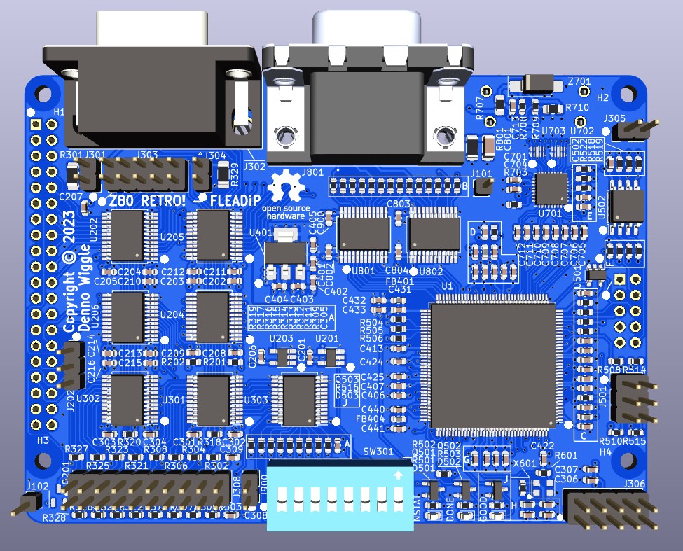
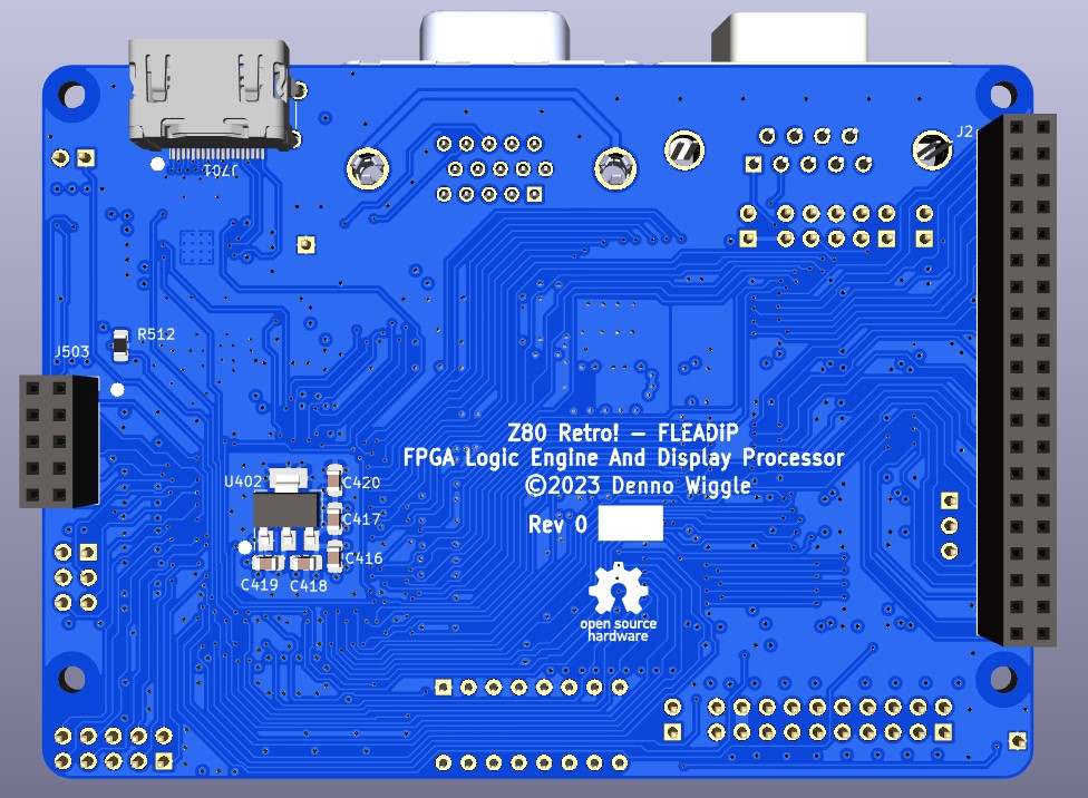
The 'output' directory contains the BOM, netlist, and PDF schematic.
Board design used KiCad 7.0.2.
The HDMI connector is on the bottom side of the board so that there is no P/N signal swap, at least for rev 0 PCB. This means the card doesn't fit right above the Z80 Retro! CPU board unless a spacer board is added or the HDMI connector is not installed. The board was designed with the intent to use the ESP32 programmer board underneath FLEADiP which does have space for the connector.
A future spin could move the HDMI connector to the top side, with swapping all P/N traces. This may work right away with no hdl code change, but if it does not the logic should be inverted in the HDL code to address this.
The silkscreen circle pin 1 marker for SW301, the 16 pin configuration switch is in the wrong position. The copper layout is fine,
J503 2x5 right-angle programming connector should be installed on the top side of the board.
To program an image to the FPGA FLASH you can use a FT232H module with the Efinity FPGA SW tool programmer.
| Signal | FT232H Module Pin | FLEADiP Location |
|---|---|---|
| SPI_CLK | AD1 | J503.2 |
| SPI_MOSI | AD0 | J503.8 |
| SPI_MISO | AD2 | J503.10 |
| SPI_CS_N | AD3 | J503.4 |
| MOUSE_RESET_N | AD4 | J503.6 |
| MOUSE_CDONE | AD5 | J503.5 |
| GND | Module Specific | J503.9 |
Efinity Programmer tool settings
The board can also be programmed with the "ESP32 Programmer and WiFi" Z80 Retro! add on board which offers console xmodem and web based upload options for programming files.
The second Joystick port uses a 10 pin header J303 and is designed for a 10pin header to female DB9 cable with a gender changer added. That way it's just using another Z80 Retro! console cable with addition of DB9 gender changer rather than a totally new cable.
1x2 pin headers that supply 5V if a jumper is installed on the joystick ports should be no stuff for normal operation.
The second joystick fire/button2 and 5V options are wired per MSX joystick form factor.
The schematic design and BOM uses a T20QFP144 device with C3 timing. It is recommended to switch to a C4 part as it has significantly more timing margin in the logic design. DigiKey part number is 2134-T20Q144C4-ND. An I4 device is also a good choice .
| Qty | Value | Footprint | References |
|---|---|---|---|
| 63 | 100nF | Capacitor_SMD:C_0603_1608Metric | C201, C204, C205, C206, C208, C209, C211, C212, C213, C214, C301, C302, C303, C304, C305, C306 +47 |
| 53 | 10K | Resistor_SMD:R_0603_1608Metric | R201, R202, R302, R303, R304, R305, R306, R307, R308, R309, R310, R311, R312, R313, R314, R315 +37 |
| 20 | 10uF | Capacitor_SMD:C_0603_1608Metric | C202, C203, C207, C210, C215, C216, C307, C309, C401, C402, C405, C406, C421, C433, C434, C436 +4 |
| 9 | SN74LVC8T245DBR | Package_SO:SSOP-24_5.3x8.2mm_P0.65mm | U202, U204, U205, U206, U301, U302, U303, U801, U802 |
| 5 | BLM18AG601SN1D | Inductor_SMD:L_0603_1608Metric | FB401, FB402, FB403, FB404, FB601 |
| 4 | 1K | Resistor_SMD:R_0603_1608Metric | R501, R502, R503, R516 |
| 4 | Conn_01x02 | Connector_PinHeader_2.54mm:PinHeader_1x02_P2.54mm_Vertical | J301, J304, J305, J900 |
| 4 | MMUN2211LT1G | Package_TO_SOT_SMD:SOT-23-3 | Q201, Q501, Q502, Q503 |
| 4 | MountingHole | MountingHole:MountingHole_2.7mm_M2.5_DIN965 | H1, H2, H3, H4 |
| 3 | 10uF | Capacitor_SMD:C_0805_2012Metric_Pad1.18x1.45mm_HandSolder | C416, C417, C420 |
| 3 | 1K00 | Resistor_SMD:R_0603_1608Metric | R804, R808, R812 |
| 3 | 2K00 | Resistor_SMD:R_0603_1608Metric | R803, R807, R811 |
| 3 | 499R | Resistor_SMD:R_0603_1608Metric | R805, R809, R813 |
| 3 | 4K02 | Resistor_SMD:R_0603_1608Metric | R802, R806, R810 |
| 3 | LTST-C191KRKT | LED_SMD:LED_0603_1608Metric | D501, D502, D503 |
| 2 | 100R | Resistor_SMD:R_1206_3216Metric_Pad1.30x1.75mm_HandSolder | R301, R329 |
| 2 | 100R | Resistor_SMD:R_0603_1608Metric | R814, R815 |
| 2 | 100nF | Capacitor_SMD:C_0805_2012Metric_Pad1.18x1.45mm_HandSolder | C418, C419 |
| 2 | 12K4 | Resistor_SMD:R_0603_1608Metric | R704, R706 |
| 2 | 33R | Resistor_SMD:R_0603_1608Metric | R601, R705 |
| 2 | Conn_01x01 | Connector_PinHeader_2.54mm:PinHeader_1x01_P2.54mm_Vertical | J101, J102 |
| 2 | Conn_02x05 | Connector_PinHeader_2.54mm:PinHeader_2x05_P2.54mm_Vertical | J303, J306 |
| 2 | Logo_Open_Hardware_Small | Symbol:OSHW-Logo_7.5x8mm_SilkScreen | LOGO101, LOGO102 |
| 2 | RCLAMP0524P | digikey-footprints:UFDFN-10_2.5x1mm | U702, U703 |
| 2 | SN74LVC1G125DBVR | Package_TO_SOT_SMD:SOT-23-5_HandSoldering | U201, U203 |
| 1 | 0R | Resistor_SMD:R_0805_2012Metric_Pad1.20x1.40mm_HandSolder | R512 |
| 1 | 1M | Resistor_SMD:R_1206_3216Metric | R801 |
| 1 | 1nF | Capacitor_SMD:C_1206_3216Metric | C801 |
| 1 | 2K7 | Resistor_SMD:R_0805_2012Metric_Pad1.20x1.40mm_HandSolder | R710 |
| 1 | Conn_01x03 | Connector_PinHeader_2.54mm:PinHeader_1x03_P2.54mm_Vertical | J202 |
| 1 | Conn_02x03 | Connector_PinHeader_2.54mm:PinHeader_2x03_P2.54mm_Vertical | J501 |
| 1 | Conn_02x05 | Connector_PinSocket_2.54mm:PinSocket_2x05_P2.54mm_Vertical | J503 |
| 1 | Conn_02x10_Odd_Even | Connector_PinHeader_2.54mm:PinHeader_2x10_P2.54mm_Vertical | J308 |
| 1 | Conn_02x20_Counter_Clockwise | WTM_Library:PinSocket_2x20_P2.54mm_Vertical_clockwise | J2 |
| 1 | DB9_Male_MountingHoles | Connector_Dsub:DSUB-9_Male_Horizontal_P2.77x2.84mm_EdgePinOffset7.70mm_Housed_MountingHolesOffset9.12mm | J302 |
| 1 | DNL | Resistor_SMD:R_0805_2012Metric_Pad1.20x1.40mm_HandSolder | R707 |
| 1 | ECS-2333-500-BN-TR | Oscillator:Oscillator_SMD_EuroQuartz_XO32-4Pin_3.2x2.5mm | X601 |
| 1 | HDMI_A_1.4 | Connector_HDMI:HDMI_A_Amphenol_10029449-x01xLF_Horizontal | J701 |
| 1 | ICD15S13E4GX00LF | WTM_Library:AMPHENOL_ICD15S13E4GX00LF | J801 |
| 1 | PTN3366BSMP | Package_DFN_QFN:HVQFN-32-1EP_5x5mm_P0.5mm_EP3.1x3.1mm_ThermalVias | U701 |
| 1 | SN74LVC1G08DBVR | Package_TO_SOT_SMD:SOT-23-5 | U501 |
| 1 | SW_DIP_x08 | Button_Switch_THT:SW_DIP_SPSTx08_Slide_9.78x22.5mm_W7.62mm_P2.54mm | SW301 |
| 1 | T20Q144C3 | Package_QFP:LQFP-144_20x20mm_P0.5mm | U1 |
| 1 | TLV1117LV12DCYR | Package_TO_SOT_SMD:SOT-223 | U402 |
| 1 | TLV1117LV33DCYR | Package_TO_SOT_SMD:SOT-223 | U401 |
| 1 | TVS_SMAJ5.0A | Diode_SMD:D_SMA_Handsoldering | Z701 |
| 1 | W25Q32JVSS | Package_SO:SOIC-8_5.23x5.23mm_P1.27mm | U502 |
It measures 100 × 72 mm and has 4 copper layers, 1.6 mm thick.
226 parts, built around the T20Q144C3, SN74LVC1G125DBVR-TP, PTN3366BSMP and W25Q32JVSSIQ. The full list of its parts is on this page, with links to each part's symbol and footprint where PCBKit's library has them.
From the dennowiggle/FLEADiP repository on GitHub, at the commit this page was made from: the board is kicad/FLEADiP.kicad_pcb and its schematic kicad/FLEADiP.kicad_sch. PCBKit opens the board in the browser, with nothing to install.
Its repository publishes it under the LGPL-2.1 licence: you may reuse it on that licence's terms (keep the author's notice, and for a copyleft licence share your changes alike).
dennowiggle/Retro-PETER
3.3V Retro computer project => FPGA + RCBUS + CPU boards making a custom system.

dennowiggle/Z8S180-WTM
Repository for sharing Z8S180-WTM design changes only. A private repository.


filliformes/pandore
pandore is an open-source digital audio instrument protyping platform based on the LattePanda Mu.


