2 layers60 × 110 mm
 dchwebb/Retrospector18
Eurorack Delay Effect
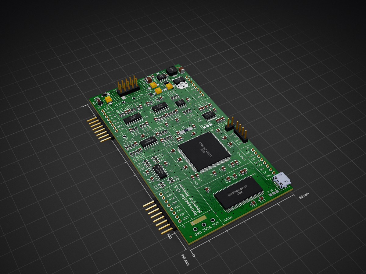
Retrospector Components is an open-source printed circuit board by dchwebb, from the dchwebb/Retrospector repository on GitHub. It is a 4-layer board of 60 × 110 mm with 149 parts on 182 nets, routed with 1,596 tracks and 349 vias.
It is built around the MCP6004-E/P, LM2675M-5.0 and TL072, with the IS42S16800F-7TLI and PCM5100APW among its other parts. Its parts include 62 capacitors, 46 resistors, 10 ICs, 8 connectors and 4 diodes. It belongs with the audio and music boards and the STM32 boards of this library.


Retrospector is a Eurorack format stereo digital delay.
Delay times can be set clocked or free-running and left and right channels can be independent or the right channel set as a multiple of the left channel. The delay times are switchable between short, long and reversed with maximum delay times over 5 minutes.
The feedback path can be filtered with settings allowing a sweep from low pass to high pass, or either separately. The delayed signal can be modulated for subtle chorussing effects or left and right channels fed back into each other to widen dual mono sources.
The feedback control allows greater than 100% regeneration allowing the delay to increase the volume of the delayed signal.
Three RGB LEDs display the delay times (using different colours to indicate clocking and channel linking) and the filter status (white to red with increasing low pass filtering and white to blue for high pass).
A USB port is available on the rear of the module providing configuration, debug and upgrade options via a serial interface.
The module is constructed from a sandwich of three PCBs. The front panel is held to the control PCB using the potentiometers and jack sockets with light guides directing the RGB LEDs from the control PCB. The control PCB also houses the LED driver. All other components are on the component PCB and this is attached to the control PCB with standard 2.54mm headers. The component board is a 4 layer PCB; the others have 2 layers.
Retrospector is built around an STM32H743 microcontroller clocked at 400MHz. The MCU uses a pair of multi-channel 16-bit ADCs to digitise the stereo audio input signal and the various potentiometer and control voltage inputs.
The MCU controls the external DAC with I2S at 16 bits. The MCU's internal 12-bit DACs are used to control the linear VCA that carries out stereo mixing of the digital wet signal and analog dry signal.
Delay samples are held in external 32MB SDRAM controlled by the MCU's FMC peripheral. The MCU's internal memory is mainly used for DMA buffers and FIR filter buffers (better performance than the slower external RAM). The MCU also has both data and instruction caches which are used to greatly improve performance.
The three RGB LEDs are controlled by a Toshiba 9 channel LED driver (TB62781FNG) with the MCU setting colour and brightness over SPI and DMA.
The MCU also supports a USB micro-B port to allow upgrades, configuration and debugging via a serial console:


A) A switched-mode power supply (Texas Instruments LM2675) converts the 12V rail to 5V which is then converted to 3.3V using an LDO. THe 5V rail also powers the RGB LEDs.
B) The mix control uses a 4 channel linear VCA (Alfa AS3364D) to control the Wet/Dry mix. This keeps the dry signal analog throughout.
C) The Output signals are mixed and inverted (to preserve signal polarity) with a TL074 and a TL072 op-amp.
D) The digital Wet signal is converted to analog using a Texas Instruments PCM5100 DAC.
E) The analog input signals (audio and control voltage) are scaled and mixed using a pair of MCP6004 op-amps.
F) The microcontroller is an STM32H743 running at 400MHz.
G) The delay beffers are stored in an external 32MB RAM module (ISSI IS42S16160J) allowing for over 5 minutes of stereo delay.
There were two errors on v2 hardware:
| Qty | Value | Footprint | References |
|---|---|---|---|
| 26 | 100nF | Capacitors_SMD:C_0603_HandSoldering | C2, C3, C10, C11, C12, C13, C14, C15, C16, C17, C18, C19, C20, C21, C37, C38 +10 |
| 9 | 47k | Resistors_SMD:R_0603_HandSoldering | R2, R6, R7, R10, R11, R18, R22, R24, R33 |
| 7 | 2.2uF | Capacitors_SMD:C_0603_HandSoldering | C24, C25, C42, C46, C48, C59, C60 |
| 7 | TestPoint | Measurement_Points:Measurement_Point_Square-SMD-Pad_Small | TP7, TP8, TP9, TP10, TP11, TP12, TP13 |
| 6 | 1.5nF | Capacitors_SMD:C_0603_HandSoldering | C22, C27, C28, C33, C34, C36 |
| 6 | 10k | Resistors_SMD:R_0603_HandSoldering | R9, R15, R25, R28, R31, R34 |
| 6 | 30k | Resistors_SMD:R_0603_HandSoldering | R20, R30, R37, R38, R39, R40 |
| 6 | TestPoint | Custom_Footprints:1.3mm_Test_Point | TP1, TP2, TP3, TP4, TP5, TP6 |
| 4 | 100k | Resistors_SMD:R_0603_HandSoldering | R19, R26, R27, R35 |
| 4 | 100pF | Capacitors_SMD:C_0603_HandSoldering | C1, C26, C32, C35 |
| 4 | 510R | Resistors_SMD:R_0603_HandSoldering | R41, R42, R43, R44 |
| 4 | 560pF | Capacitors_SMD:C_0603_HandSoldering | C49, C50, C51, C52 |
| 4 | Conn_01x08_Male | Pin_Headers:Pin_Header_Straight_1x08_Pitch2.54mm | J1, J2, J3, J4 |
| 3 | 10uF | Capacitors_SMD:C_0805 | C39, C41, C47 |
| 3 | 1N5819 | Diodes_SMD:D_SOD-123 | D1, D2, D3 |
| 3 | 2k2 | Resistors_SMD:R_0603_HandSoldering | R8, R14, R46 |
| 3 | 68k | Resistors_SMD:R_0603_HandSoldering | R21, R23, R32 |
| 2 | 10nF | Capacitors_SMD:C_0603_HandSoldering | C45, C56 |
| 2 | 1k | Resistors_SMD:R_0603_HandSoldering | R29, R36 |
| 2 | 1nF | Capacitors_SMD:C_0603_HandSoldering | C23, C30 |
| 2 | 20k | Resistors_SMD:R_0603_HandSoldering | R3, R12 |
| 2 | 22uF | Capacitors_SMD:CP_Elec_4x5.8 | C57, C62 |
| 2 | 30pF | Capacitors_SMD:C_0603_HandSoldering | C29, C31 |
| 2 | 47uF | Capacitors_SMD:CP_Elec_5x5.8 | C43, C61 |
| 2 | 6k8 | Resistors_SMD:R_0603_HandSoldering | R4, R13 |
| 2 | 91k | Resistors_SMD:R_0603_HandSoldering | R5, R16 |
| 2 | JLC_Tooling_Hole | Custom_Footprints:JLC_SMT_Tooling_Hole | H1, H2 |
| 2 | MCP6004 | SMD_Packages:SOIC-14_N | U1, U3 |
| 1 | 100R | Resistors_SMD:R_0603_HandSoldering | R45 |
| 1 | 22uF | Capacitors_SMD:C_1210 | C54 |
| 1 | 47uF | Capacitors_SMD:C_1210 | C55 |
| 1 | 4_Layer_Markers | Custom_Footprints:4_Layer_Markers | 4_Layer_Marker |
| 1 | 56k | Resistors_SMD:R_0603_HandSoldering | R17 |
| 1 | 68uH | Custom_Footprints:TDK_Inductor_6.9x7.2 | L1 |
| 1 | 75k | Resistors_SMD:R_0603_HandSoldering | R1 |
| 1 | 8MHz 20pF | Crystals:Crystal_SMD_5032-2pin_5.0x3.2mm_HandSoldering | Y1 |
| 1 | AS3364 | Housings_SOIC:SOIC-16_3.9x9.9mm_Pitch1.27mm | U7 |
| 1 | Eurorack_10_pin_power | Custom_Footprints:Eurorack_10_pin_header | J7 |
| 1 | I2C_TestPoint | Pin_Headers:Pin_Header_Straight_1x02_Pitch2.54mm | J8 |
| 1 | IS42S16800F-7TLI | Custom_Footprints:TSOP-II-54_22.2x10.16mm_P0.8mm | U4 |
| 1 | L | Inductors_SMD:L_0805_HandSoldering | L2 |
| 1 | LD1117-3.3-4Tab | TO_SOT_Packages_SMD:SOT-223-3_TabPin2 | U10 |
| 1 | LM2675M-5 | Housings_SOIC:SOIC-8_3.9x4.9mm_Pitch1.27mm | U9 |
| 1 | LM4040DBZ-5 | TO_SOT_Packages_SMD:SOT-23 | D4 |
| 1 | PCM5100APW | Custom_Footprints:SSOP-20_4.4x6.5mm_Pitch0.65mm_Round_Pads | U8 |
| 1 | STM32H743ZITx | Package_QFP:LQFP-144_20x20mm_P0.5mm | U5 |
| 1 | SWD_Header | Custom_Footprints:SWD_header | J5 |
| 1 | TL072 | Housings_SOIC:SOIC-8_3.9x4.9mm_Pitch1.27mm | U6 |
| 1 | TL074 | SMD_Packages:SOIC-14_N | U2 |
| 1 | USB_B_Micro | Custom_Footprints:USB_Micro-B_Amphenol | J6 |

dchwebb/Addatone
Eurorack Additive Oscillator based on Lattice FPGA and ARM MCU


dchwebb/Kishoof
Eurorack Wavetable Synthesizer; Dual channel; 64MB internal storage accessed via USB


mnemocron/FHNW-Pro4E-FS19T8-3DPrinterBoard-STM32
Marlin 2.0 compatible 3D printer board based on STM32F103 (KiCad)
It measures 60 × 110 mm and has 4 copper layers, 1.6 mm thick.
149 parts, built around the MCP6004-E/P, LM2675M-5.0, TL072 and IS42S16800F-7TLI. The full list of its parts is on this page, with links to each part's symbol and footprint where PCBKit's library has them.
From the dchwebb/Retrospector repository on GitHub, at the commit this page was made from: the board is Hardware/Retrospector_Components.kicad_pcb and its schematic Hardware/Retrospector_Components.kicad_sch. PCBKit opens the board in the browser, with nothing to install.
Its repository states no licence, so its author keeps all rights: ask dchwebb before reusing the design.