2 layers100 × 110 mm
AddaTone Solder Stencil
dchwebb/Addatone
Eurorack Additive Oscillator based on Lattice FPGA and ARM MCU
81 parts13
 dchwebb/Addatone13
Eurorack Additive Oscillator based on Lattice FPGA and ARM MCU
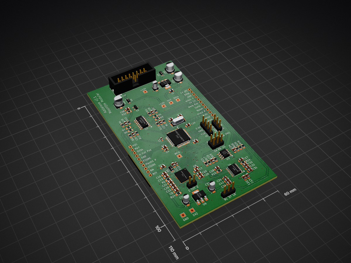
AddaTone components is an open-source printed circuit board by dchwebb, from the dchwebb/Addatone repository on GitHub. It is a 2-layer board of 60 × 110 mm with 95 parts on 124 nets, routed with 614 tracks and 117 vias.
It is built around the ICE40UP5K-SG48ITR50, MCP6004-E/P and TL072, with the LD1117S12TR-HXY, LM1117-3.3 and PCM5100APW among its other parts. Its parts include 43 capacitors, 23 resistors, 8 connectors, 7 ICs and 4 diodes. It belongs with the fPGA and programmable logic and audio and music boards and the STM32 and FPGA and CPLD boards of this library.


Addatone is a Eurorack oscillator using additive synthesis. It is a two channel oscillator with channel one outputting fundamental and odd harmonics and channel two fundamental and even harmonics.
Each channel has potentiometer and CV control over the number of harmonics with higher harmonics progressively attenuated. In addition a 'Count' pot and CV input hard-limit the total number of audible harmonics. A warp control progressively detunes the odd harmonics up and even harmonics down.
Channel one has a mix switch which allows a mix of both channels to be output from channel one. Channel two has a multiply switch which allows a multiple of both channels to be output from channel two (ie a ring modulation effect).
The final controls are an octave potentiometer covering a five octave range and a fine tune control covering around an octave.

The core sound generator is an ICE40UP5K FPGA from Lattice. This is responsible for generating the harmonics, mixing/multiplying and then outputting to the DAC via I2S protocol.
The module also contains an STM32F446 microcontroller which holds the FPGA bitstream in internal flash memory; this is used to program the FPGA on start-up via SPI. In addition the STM32 is used as an ADC to digitise and scale all potentiometer and CV control data. This is periodically transferred to the FPGA via SPI. The STM32 is clocked from an external 12MHz crystal. This is also used to drive the FPGA clock via the STM32 MCO (Master Clock Output) peripheral.
The DAC is a Texas Instruments PCM5100APW, operating 2 channels at 16 bits, 48kHz. Two op-amps are used to scale input CV voltages and to amplify the DAC output to Eurorack levels (8V peak to peak).
A look-up table in block RAM (Sine_LUT) holds 2048 16 bit samples containing a single cycle sine wave. Individual harmonics are generated by traversing the LUT at a speed relative to the harmonic frequency.
The SamplePos_RAM 256 x 16 bit look-up table holds the current Sine LUT position of each harmonic. This position is advanced according to the harmonic's frequency at each sample and the sine sample is scaled and added to an accumulator. The initial values of the sample position LUT are pre-calculated to minimise 'crest factor'. If each harmonic started at position 0 of a sine wave then peaks and troughs would coincide to create a wave with an amplitude greater than the dynamic range of the system.
A graphical javascript tool to visualise and calculate minimal crest factor sample positions is available here: https://htmlpreview.github.io/?https://raw.githubusercontent.com/dchwebb/Addatone/master/SamplePosLUT/SineLUT.htm
The FPGA receives its control data from the ADCs processed in the STM32. These are periodically sent via SPI and decoded using a custom peripheral (ADC_SPI_In).
The DAC_I2S module is a custom peripheral used to dispatch the final sample values to the DAC via the I2S protocol.
The 12MHz clock received from the STM32 MCO is scaled to the ICE40's maximum clock frequency of 48MHz.
The ICE40 bitstream is developed in Lattice's Radiant IDE. Full source code here: https://github.com/dchwebb/Addatone/tree/master/Addatone_ICE40
The module includes an STM32F446 MCU that carries out various helper roles. The firmware was developed in STM's CubeIDE and available here: https://github.com/dchwebb/Addatone/tree/master/Addatone_STM32F446
The FPGA bitstream is stored in the MCU's flash memory and is programmed into the FPGA at startup using an STM32 SPI peripheral (see fpgaHandler::ProgramBitstream method). Once the FPGA is programmed the ADC data derived from external CV control and potentiometers is processed, scaled and transmitted in a periodic packet to the FPGA via SPI (see fpgaHandler::SendControls method).
The 'calib' button allows the setting of the mid point of the fine tune and the spread of the tuning. To start calibration turn the Octave and Fine Tune knobs to their mid point position.
Press the Calib button. Changing the Fine Tune knob will alter the pitch. Turning the Octave knob clockwise will decrease the tuning spread, and vice versa.
When calibration is complete press the Calib button again. Turning the Fine Tune knob to the center position should set the correct pitch.
To erase the configured calibration hold the Calib button down when powering on the module.
| Qty | Value | Footprint | References |
|---|---|---|---|
| 11 | 100nF | Capacitor_SMD:C_0805_2012Metric_Pad1.18x1.45mm_HandSolder | C8, C10, C11, C13, C14, C17, C19, C24, C25, C26, C38 |
| 7 | TestPoint | TestPoint:TestPoint_THTPad_2.0x2.0mm_Drill1.0mm | TP1, TP2, TP3, TP4, TP5, TP6, TP7 |
| 5 | 100nF | Capacitor_SMD:C_0603_1608Metric_Pad1.08x0.95mm_HandSolder | C1, C4, C9, C15, C35 |
| 4 | 100k | Resistor_SMD:R_0805_2012Metric_Pad1.20x1.40mm_HandSolder | R3, R5, R7, R9 |
| 4 | 10nF | Capacitor_SMD:C_0805_2012Metric_Pad1.18x1.45mm_HandSolder | C6, C7, C12, C20 |
| 3 | 10uF | Capacitor_SMD:CP_Elec_3x5.3 | C36, C37, C42 |
| 3 | 10uF | Capacitor_SMD:C_0805_2012Metric_Pad1.18x1.45mm_HandSolder | C16, C22, C43 |
| 3 | 2.2k | Resistor_SMD:R_0805_2012Metric_Pad1.20x1.40mm_HandSolder | R14, R15, R22 |
| 3 | 2.2uF | Capacitor_SMD:C_0805_2012Metric_Pad1.18x1.45mm_HandSolder | C5, C31, C33 |
| 3 | 47k | Resistor_SMD:R_0805_2012Metric_Pad1.20x1.40mm_HandSolder | R10, R12, R13 |
| 2 | 1.5nF | Capacitor_SMD:C_0805_2012Metric_Pad1.18x1.45mm_HandSolder | C27, C30 |
| 2 | 100pF | Capacitor_SMD:C_0805_2012Metric_Pad1.18x1.45mm_HandSolder | C23, C34 |
| 2 | 10k | Resistor_SMD:R_0805_2012Metric_Pad1.20x1.40mm_HandSolder | R16, R17 |
| 2 | 1N5819 | Diode_SMD:D_SOD-123 | D3, D4 |
| 2 | 1k | Resistor_SMD:R_0805_2012Metric_Pad1.20x1.40mm_HandSolder | R20, R21 |
| 2 | 1nF | Capacitor_SMD:C_0805_2012Metric_Pad1.18x1.45mm_HandSolder | C18, C32 |
| 2 | 2.2nF | Capacitor_SMD:C_0805_2012Metric_Pad1.18x1.45mm_HandSolder | C28, C29 |
| 2 | 22uF | Capacitor_SMD:CP_Elec_5x5.3 | C39, C40 |
| 2 | 30pF | Capacitor_SMD:C_0805_2012Metric_Pad1.18x1.45mm_HandSolder | C2, C3 |
| 2 | 33k | Resistor_SMD:R_0805_2012Metric_Pad1.20x1.40mm_HandSolder | R18, R19 |
| 2 | 68k | Resistor_SMD:R_0805_2012Metric_Pad1.20x1.40mm_HandSolder | R6, R8 |
| 2 | Conn_01x03_Male | Connector_PinHeader_2.54mm:PinHeader_1x03_P2.54mm_Vertical | J4, J6 |
| 1 | 100 | Resistor_SMD:R_0805_2012Metric_Pad1.20x1.40mm_HandSolder | R1 |
| 1 | 120 | Resistor_SMD:R_0805_2012Metric_Pad1.20x1.40mm_HandSolder | R24 |
| 1 | 1uF | Capacitor_SMD:C_0805_2012Metric_Pad1.18x1.45mm_HandSolder | C21 |
| 1 | 47uF | Capacitor_SMD:CP_Elec_5x5.3 | C41 |
| 1 | 56k | Resistor_SMD:R_0805_2012Metric_Pad1.20x1.40mm_HandSolder | R11 |
| 1 | 82k | Resistor_SMD:R_0805_2012Metric_Pad1.20x1.40mm_HandSolder | R2 |
| 1 | 91k | Resistor_SMD:R_0805_2012Metric_Pad1.20x1.40mm_HandSolder | R4 |
| 1 | Conn_01x02_Male | Connector_PinHeader_2.54mm:PinHeader_1x02_P2.54mm_Vertical | J7 |
| 1 | Conn_01x06_Male | Connector_PinHeader_2.54mm:PinHeader_2x03_P2.54mm_Vertical | J5 |
| 1 | Conn_01x10_Female | Connector_PinSocket_2.54mm:PinSocket_1x10_P2.54mm_Vertical | J2 |
| 1 | Conn_01x12_Female | Connector_PinSocket_2.54mm:PinSocket_1x12_P2.54mm_Vertical | J3 |
| 1 | ECS-12MHz | Crystals:Crystal_SMD_0603-2pin_6.0x3.5mm_HandSoldering | Y1 |
| 1 | Eurorack_16_pin_power | Custom_Footprints:Eurorack_16_pin_header | J8 |
| 1 | ICE40UP5K-SG48ITR | Custom_Footprints:ICE40_QFN-48-1EP_7x7mm_Pitch0.5mm | U2 |
| 1 | Jumper_2_Bridged | Jumper:SolderJumper-2_P1.3mm_Bridged_Pad1.0x1.5mm | JP1 |
| 1 | L | Inductor_SMD:L_0805_2012Metric_Pad1.15x1.40mm_HandSolder | L1 |
| 1 | LD1117S12TR | Package_TO_SOT_SMD:SOT-223 | U6 |
| 1 | LM1117-3.3 | Package_TO_SOT_SMD:SOT-223 | U7 |
| 1 | LM4040DBZ-5 | Package_TO_SOT_SMD:SOT-23 | D2 |
| 1 | MBR130T1G | Diode_SMD:D_SOD-123 | D1 |
| 1 | MCP6004 | Package_SO:SOIC-14_3.9x8.7mm_P1.27mm | U3 |
| 1 | PCM5100APW | Custom_Footprints:SSOP-20_4.4x6.5mm_Pitch0.65mm_Round_Pads | U4 |
| 1 | STM32F446RETx | Package_QFP:LQFP-64_10x10mm_P0.5mm | U1 |
| 1 | SWD_Header | Custom_Footprints:SWD_header | J1 |
| 1 | TL072 | Package_SO:SOIC-8_3.9x4.9mm_P1.27mm | U5 |
dchwebb/Addatone
Eurorack Additive Oscillator based on Lattice FPGA and ARM MCU

dchwebb/Addatone
Eurorack Additive Oscillator based on Lattice FPGA and ARM MCU

dchwebb/Addatone
Eurorack Additive Oscillator based on Lattice FPGA and ARM MCU


dchwebb/Kishoof
Eurorack Wavetable Synthesizer; Dual channel; 64MB internal storage accessed via USB


mmalex/wagyu
hardware & software for a simple eurorack module to support some youtube livestreams
It measures 60 × 110 mm and has 2 copper layers, 1.6 mm thick.
95 parts, built around the ICE40UP5K-SG48ITR50, MCP6004-E/P, TL072 and LD1117S12TR-HXY. The full list of its parts is on this page, with links to each part's symbol and footprint where PCBKit's library has them.
From the dchwebb/Addatone repository on GitHub, at the commit this page was made from: the board is Hardware/AddaTone components.kicad_pcb and its schematic Hardware/AddaTone components.kicad_sch. PCBKit opens the board in the browser, with nothing to install.
Its repository states no licence, so its author keeps all rights: ask dchwebb before reusing the design.