2 layers73 × 55 mm
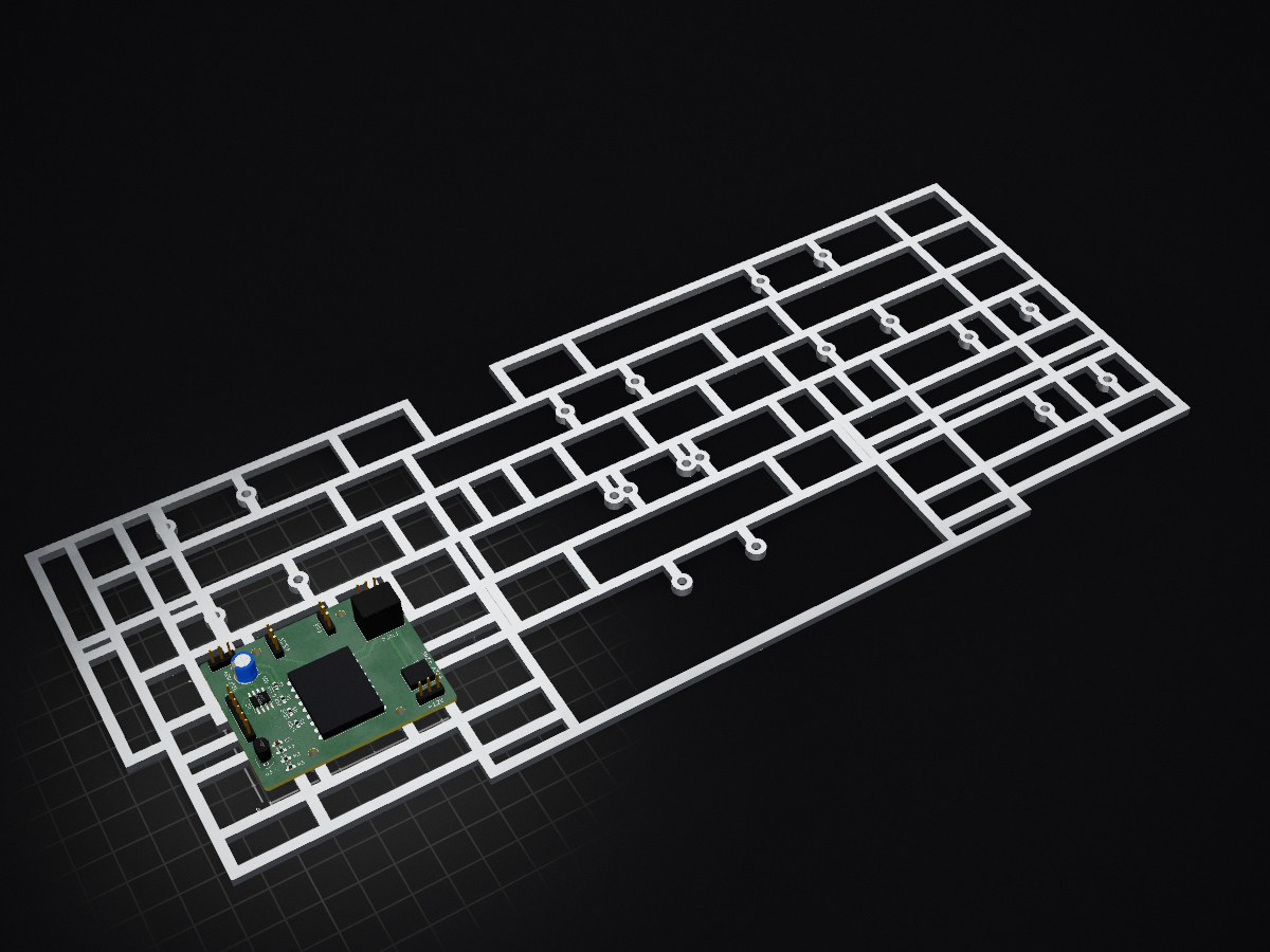
 David-EIPI/esp32-zigbee-shade1
Outdoor roller window covering using ESP32-H2 and Zigbee Home Assistant integration
Motor esp32h2 is an open-source printed circuit board by David-EIPI, from the David-EIPI/esp32-zigbee-shade repository on GitHub, published under the BSD-2-Clause licence. It is a 2-layer board of 55.9 × 45.7 mm with 24 parts on 32 nets, routed with 162 tracks and 3 vias.
It is built around the R-78E5.0-1.0, DRV8871DDA and 0.1UF 50V 5*11. Its parts include 6 resistors, 6 connectors, 3 capacitors and 3 ICs. It belongs with the radio and wireless and home automation and IoT boards and the ESP32 and RISC-V boards of this library.


This external window shade is designed to shield the room from sunlight, reducing the load on the air conditioner. I upgraded a basic corded roller shade by integrating a small DC motor and a Zigbee controller compatible with my Home Assistant network.
The firmware is written in C and built using idf.py.
It exposes 2 endpoints with 3 clusters:
The temperature sensor reports via Zigbee to monitor the temperature inside the control box, as summer ambient temperatures often exceed 35°C, and the enclosure tightly houses both the ESP32 and the motor driver.
See here instructions on building the firmware using idf.py on Linux.
This window cover is based on the VICLLAX 5×6 ft corded roll-up shade, which uses an aluminum tube with a 1 1/8" (28 mm) inner diameter.
Several inexpensive DC motors with pre-assembled gearheads are available online, commonly found as clones of the Bringsmart High Torque Worm Gear DC motor. Most of these motors use gearheads with D-shaped shafts, predominantly 8 mm but occasionally 6 mm.
These motors and gearboxes come in various voltages and torque ratings. I used a 12 V motor equipped with a 200× ratio gearbox rated for 4 kg·cm torque. This choice turned out to be excessive, as a gearbox with a 60× or 80× ratio would have been sufficient.
To couple the motor to the roller tube, I repurposed Zemismart’s replacement 28 mm nylon gears, removing one tooth from each side and filing the D-shaped channel to match the motor shaft.
The original gear compared to the modified gear (two teeth removed, D-shape filed).
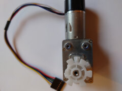
Gear mounted on the motor shaft.
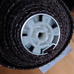
Gear inserted into the shade tube.
For motor mounting, I modified the original bracket supplied with the shade. I broke off the support lip, drilled two additional holes, and added a countersunk hole at the existing cut. The modified bracket is shown below:
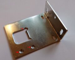
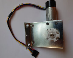
The image below shows the fully assembled motor with the coupling gear:
The control system uses an ESP32-H2 chip on Tenstar’s Supermini board (or a clone). This board sometimes exhibits startup issues when powered from a standalone DC-DC converter. Although the board already has an RC circuit on its reset line, it is apparently insufficient, as intermittent boot failures occur on power-up. I resolved this issue by soldering an additional 0.22 µF capacitor in parallel with the existing one.
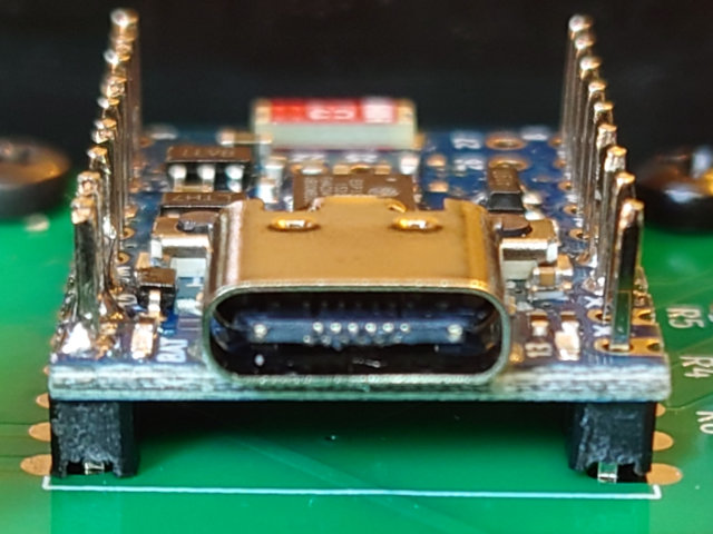
The ESP32-H2 Supermini clones available on Aliexpress vary. The most notable difference is component placement: some boards have all components mounted on the top side, while other (usually cheaper) versions have components on both sides. For the double-sided boards, the additional capacitor should be soldered on the bottom side, as shown in the photo. Although I only had 0603-sized capacitors at hand, it fit comfortably next to the existing one.
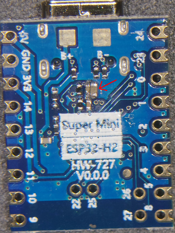
Due to bottom-side components, the ESP32-H2 board must be mounted above the mainboard:
The motor driver uses a DRV8871 chip from Texas Instruments. It accepts a PWM control signal, easily generated using the standard ESP32 ledc controller.
The motor features a rotary encoder interfaced to the ESP32’s standard pulse-counter controller. This encoder maintains consistent upper and lower travel limits and allows precise partially-open positioning of the shade.
A notable drawback of this motor is its hardwired, non-weatherproof cable. Its durability in summer humidity remains uncertain, and some corrosion is likely inevitable. To minimize electrochemical corrosion, I designed the control circuit to disconnect power from the motor and encoder when the shade is stationary.
The final assembly fits neatly into the Serpac 110i BK enclosure. I only needed to cut openings for the 6-pin motor connector (on the left) and the power jack (on the right):
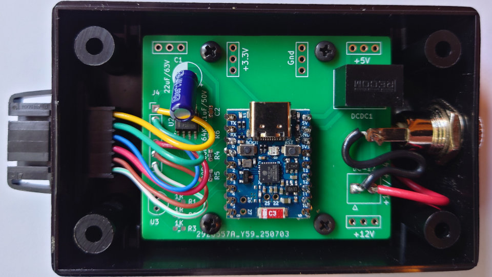
Since the motor connector is not polarized it may be a good idea to mark the connector orientation on the enclosure side.
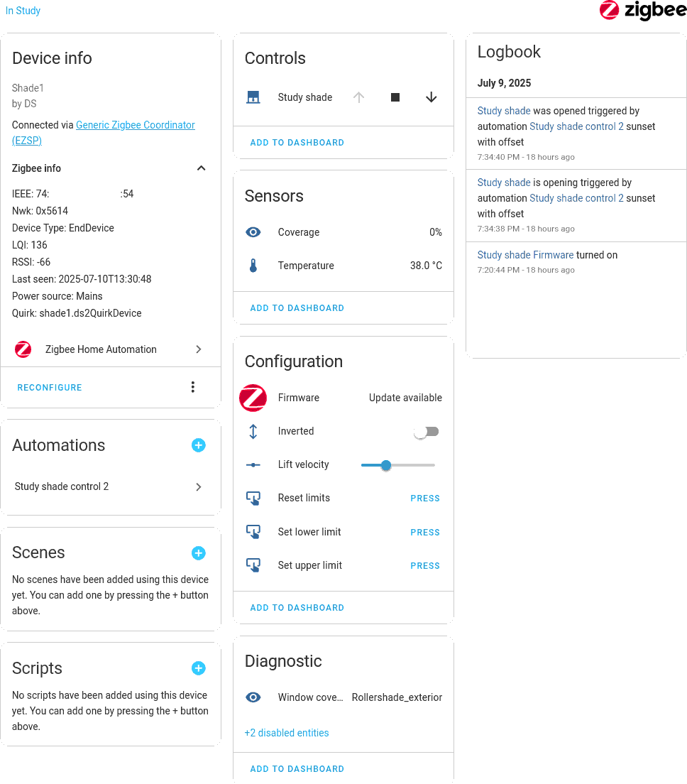
Although ZHA supports window coverings, additional configuration using a quirk is required. The quirk provides coverage percentage display, lift velocity settings, and essential calibration buttons for setting upper and lower limits.
The screenshot below shows the device page (quirk applied):
Calibration of limits must be completed before using the shade for the first time. The calibration procedure is as follows:
Depending on Zigbee network topology, commands may take about a second to process. Thus, if the motor rolls quickly, reducing the lift velocity before calibration may improve accuracy.
The firmware supports OTA upgrades. ESP's Zigbee library handles most tasks, leaving only four essential esp_ota_* function calls (begin, data, write, and end) for firmware implementation, aside from cluster allocation and error checking. The SDK provides an image builder tool (image_builder_tool.py) to convert compiled firmware into OTA format (see the ota_image.sh script for a usage example).
On the Home Assistant side, the Zigpy configuration should be added to configuration.yaml under the zha: section, as illustrated below:
zha:
  zigpy_config:
    ota:
      extra_providers:
        - type: zigpy_local
          index_file: /config/zha_ota/local_index.json
        - type: advanced
          warning: I understand I can *destroy* my devices by enabling OTA
              updates from files. Some OTA updates can be mistakenly applied to the
              wrong device, breaking it. I am consciously using this at my own risk.
          path: /config/zha_ota
OTA update files (JSON and BIN) should be uploaded to the specified directory (/config/zha_ota in this example). When using the JSON OTA provider, Home Assistant will display firmware version and release notes from the provided JSON file.
| Qty | Value | Footprint | References |
|---|---|---|---|
| 5 | Conn_01x03_Pin | Connector_PinHeader_2.54mm:PinHeader_1x03_P2.54mm_Vertical | J1, J2, J3, J5, J6 |
| 4 | MountingHole | MountingHole:MountingHole_2.7mm_M2.5 | H1, H2, H3, H4 |
| 2 | 0.1uF/50V | Capacitor_SMD:C_0603_1608Metric_Pad1.08x0.95mm_HandSolder | C2, C3 |
| 2 | 100R | Resistor_SMD:R_0603_1608Metric_Pad0.98x0.95mm_HandSolder | R4, R5 |
| 2 | 1R | Resistor_SMD:R_0603_1608Metric_Pad0.98x0.95mm_HandSolder | R1, R2 |
| 1 | 1K | Resistor_SMD:R_0603_1608Metric_Pad0.98x0.95mm_HandSolder | R3 |
| 1 | 22uF/63V | Capacitor_THT:CP_Radial_D6.3mm_P2.50mm | C1 |
| 1 | 64K | Resistor_SMD:R_0603_1608Metric_Pad0.98x0.95mm_HandSolder | R6 |
| 1 | Conn_01x02 | Connector_TE-Connectivity:TE_826576-2_1x02_P3.96mm_Vertical | DC-12 |
| 1 | Conn_01x06 | Connector_PinHeader_2.54mm:PinHeader_1x06_P2.54mm_Vertical | J4 |
| 1 | DRV5055A4xLPGxQ1 | Package_TO_SOT_THT:TO-92_Inline | U3 |
| 1 | DRV8871 | Package_SO:Texas_HTSOP-8-1EP_3.9x4.9mm_P1.27mm_EP2.95x4.9mm_Mask2.4x3.1mm_ThermalVias | U2 |
| 1 | R-78E5.0-1.0 | Converter_DCDC:Converter_DCDC_RECOM_R-78E-0.5_THT | DCDC1 |
| 1 | ~ | my_rfmodule:ESP32-H2-SuperMini | U1 |
It measures 55.9 × 45.7 mm and has 2 copper layers, 1.6 mm thick.
24 parts, built around the R-78E5.0-1.0, DRV8871DDA and 0.1UF 50V 5*11. The full list of its parts is on this page, with links to each part's symbol and footprint where PCBKit's library has them.
From the David-EIPI/esp32-zigbee-shade repository on GitHub, at the commit this page was made from: the board is sch/motor-esp32h2.kicad_pcb and its schematic sch/motor-esp32h2.kicad_sch. PCBKit opens the board in the browser, with nothing to install.
Its repository publishes it under the BSD-2-Clause licence: you may reuse it on that licence's terms (keep the author's notice, and for a copyleft licence share your changes alike).


Nithin1777/PCB_DESIGNS
These are the PCB designs that I made for the robotics club and the department of electronics.

oomlout/oomlout_oomp_project_bot_v_2

westlicht/performer-hardware
PER|FORMER Eurorack Sequencer - Hardware Design Files


fwachsmuth/Filmkorn-Raw-Scanner
The Filmkorn Raw Scanner, turning 8mm and 16mm films into lossless 12-bit CinemaDNG