Skip to the content
8 layers120 × 46 mmK2 v4 8L.l5, the printed circuit board in 3D

K2 Worker Data-Plane Card — worker-side converter in the IOCONVERT V2.0 cluster. Carries two M.2 lanes via MCIO through DS160PR810 ReDrivers, folding into a SlimSAS x8 PCIe Gen4 uplink (~16 GB/s).

Size
120 × 46 mm
Copper layers
8
Thickness
1.6 mm
Parts
58
Nets
100
Pads
685
Tracks, vias
4,720, 710
Pours
18
Routed
Yes
KiCad
KiCad 10.0 (file 20260206)
Created
28 Aug 2026
Updated
5 Oct 2026

Overview

K2 v4 8L.l5 is an open-source printed circuit board by dataxcash, from the dataxcash/hw_ic_k2 repository on GitHub, published under the AGPL-3.0 licence. It is an 8-layer board of 120 × 46 mm with 58 parts on 100 nets, routed with 4,720 tracks and 710 vias.

It is built around the STM32G0B1CBT6, BAT54C and SS34. Its parts include 20 resistors, 17 capacitors, 8 connectors, 5 ICs and 2 diodes. It belongs with the computers and single-board computers boards and the STM32 boards of this library.

Main components

3

README

README.md

hw_ic_k2 — K2 PCIe Gen4 Converter Card (x8 → 2× x4)

English | 简体中文

Open-source hardware — KiCad design files for the K2 converter card, the worker-side data-plane card in the IOCONVERT V2.0 1-Master-to-4-Worker chained NTB cluster. It takes one x8 host link and fans it out to two x4 MCIO ports, redriven for PCIe Gen4 signal integrity.

Preview

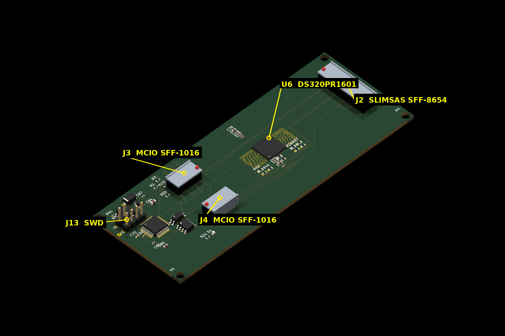
Current fabrication release (m7t8a) — annotated 3D render (connector entry directions, pin-1 markers and part labels verified against the board):

K2 PCB — 3D render, annotated (isometric)

Board file: pm_gate/artifacts/k2_v4/L6/board/k2_v4_8L.m7t8a.kicad_pcb

3D renders use KiCad stock models for standard packages. The MCIO (SFF-1016) and SlimSAS (SFF-8654) connectors have no vendor 3D models and are represented by simplified models derived from their footprint geometry (entry direction and pin-1 markers placed per footprint placement).

Overview

K2 sits between the master host and the worker devices. A single SlimSAS x8 uplink carries eight PCIe Gen4 lanes; the card redrives them (per-lane AC coupling is integrated in the device), then splits them across two MCIO 4i downlinks (4 lanes each). A single DS320PR1601 redriver (U6) handles the link, and an on-board STM32G0B1 MCU manages sideband, out-of-band UART, I2C and the FRU EEPROM.

text
                8 lanes                       2 × 4 lanes
  Master ─────────────────►  K2  ──────────────────────────► MCIO 4i (J3) → worker
  (SlimSAS x8,              │    AC coupling + redrive
   SFF-8654, J2)            └──────────────────────────────► MCIO 4i (J4) → worker

                            U6 = DS320PR1601 redriver
                            STM32G0B1 MCU · 12V DC-in

Key Features

  • Form factor: 8-layer PCB, 120 × 46 mm, 85Ω ±10% differential impedance
  • Uplink: 1× SlimSAS x8 (SFF-8654) — 8 PCIe Gen4 lanes + 2 reference clocks
  • Downlink: 2× MCIO 4i (SFF-1016) — the x8 link is bifurcated into 2× x4
  • Redrivers: single DS320PR1601 (U6); per-lane AC coupling is integrated in the device
  • Management: STM32G0B1 MCU — sideband, OOB UART, I2C, FRU EEPROM
  • Power: 12V DC-in → DC-DC 5V → LDO 3V3, plus 3.3V_AUX
  • Debug: SWD header (J13), OOB UART header (J9)

Repository Contents

PathDescription
hw/KiCad project (current 8L revision)
hw/sch/Schematics: connectors, AC-coupling & ReDriver strap (up/down), MCU & sideband, power
hw/lib/Symbol + footprint libraries
hw/data/Netlist / project configuration (YAML)
archive/k2_v4_6L/Historical 6L revision (superseded by 8L)
docs/Architecture and manufacturing notes

Getting Started

  1. Install KiCad 10.x
  2. Clone this repository
  3. Open hw/k2_v4_8L.kicad_pro
  4. If symbols/footprints show as missing, add hw/lib/DS320PR1601.kicad_sym to the symbol library table and hw/lib/ForgeOS.pretty/ to the footprint library table (global or project-level)

Key Files

FileMeaning
hw/k2_v4_8L.kicad_pcbDesign source (frozen input)
pm_gate/artifacts/k2_v4/L6/board/k2_v4_8L.m7t8a.kicad_pcbFabrication release board (ready to order)

Documentation

License

AGPL-3.0 (see LICENSE)


Part of the IOCONVERT V2.0 family: hw_ic_k1 (master gate card) · hw_ic_key (secure key vault)

Parts

58
QtyValueFootprintReferences
12100nFCapacitor_SMD:C_0402_1005MetricC73, C74, C75, C76, C77, C79, C80, C81, C82, C85, C87, C90
71KR_0603_1608MetricR36, R37, R39, R42, R43, R44, R45
44.7kResistor_SMD:R_0603_1608MetricR31, R32, R33, R34
4MountingHole_3.2mm_M3MountingHole_3.2mm_M3H1, H2, H3, H4
310KResistor_SMD:R_0603_1608MetricR1, R28, R29
31uFCapacitor_SMD:C_0603_1608MetricC78, C83, C88
2MCIO_4i_SFF1016ForgeOS:MCIO_4i_SFF-1016_RASideJ3, J4
110KR_0402_1005MetricR40
110uFCapacitor_SMD:C_0805_2012MetricC84
110µHL_0805_2012MetricL1
11KResistor_SMD:R_0603_1608MetricR21
1220RResistor_SMD:R_0603_1608MetricR3
14.7uFCapacitor_SMD:C_0603_1608MetricC86
15.6kR_0402_1005MetricR41
1BAT54CForgeOS:SOT23_BAT54CU4
1DCDC_12V_3V3Package_SO:SOIC-8_5.3x5.3mm_P1.27mmU2
1DS320PR1601DS320PR1601U6
1FRU_EEPROMForgeOS:SOIC8_FRUE2
1J_12V_INPinHeader_1x02J12
1J_EC_HEADERPinHeader_1x04J11
1J_OOB_HEADERPinHeader_1x04J9
1J_PWR_CTRLPinHeader_1x02J6
1J_SWDPinHeader_1x04J13
1LEDLED_SMD:LED_0603_1608MetricD1
1OPTO_LTV356TForgeOS:OPTO_LTV356TU5
1R_6K19R_0603_1608MetricR35
1R_8K25R_0603_1608MetricR38
1SS34D_SMAD2
1STM32G0B1CBT6MCU_STM32G0_LQFP48U1
1SlimSAS_x8_SFF8654ForgeOS:SlimSAS_x8_SFF-8654_74pin_RASideJ2

More from dataxcash/hw_ic_k2

2
  • 8 layers120 × 46 mmK2 v4 8L.l13, the printed circuit board in 3D

    K2 v4 8L.l13

    dataxcash/hw_ic_k2

    K2 Worker Data-Plane Card — worker-side converter in the IOCONVERT V2.0 cluster. Carries two M.2 lanes via MCIO through DS160PR810 ReDrivers, folding into a SlimSAS x8 PCIe Gen4 uplink (~16 GB/s).

    58 partsAGPL-3.0
  • 6 layers120 × 46 mmK2 v4.l4, the printed circuit board in 3D

    K2 v4.l4

    dataxcash/hw_ic_k2

    K2 Worker Data-Plane Card — worker-side converter in the IOCONVERT V2.0 cluster. Carries two M.2 lanes via MCIO through DS160PR810 ReDrivers, folding into a SlimSAS x8 PCIe Gen4 uplink (~16 GB/s).

    42 partsAGPL-3.0

Similar boards

  • 2 layers119.1 × 80.4 mmCandleLightfd S01 3x3, the printed circuit board in 3D

    CandleLightfd S01 3x3

    linux-automation/candleLightFD

    USB CAN-FD interface based on the STM32G0 that works well with gs_usb on Linux

    375 parts62
  • 2 layers56 × 70 mmCFS Bus Adapter R2, the printed circuit board in 3D

    CFS Bus Adapter R2

    fake-name/cfs-reverse-engineering

    Reverse engineering the Creality CFS for use as a general AMU/MMU system

    66 parts58
  • 4 layers100 × 100 mmPCAP04 Acquisition 3CH v1.5 100mm C496550, the printed circuit board in 3D

    PCAP04 Acquisition 3CH v1.5 100mm C496550

    NautyXie/pcap04-capacitance-readout

    KiCad 7 project for the PCAP04 3-channel capacitance readout board. 100 × 100 mm, 4 layers, SMA edge connectors.

    69 parts2
  • 4 layers35 × 35 mmCanonical, the printed circuit board in 3D

    Canonical

    AnasSarkiz/smart-nema14-motor-controller

    STEPPERONLINE 14HM11-0404S controller — unrouted work-in-progress prototype; mechanical and electrical qualification pending

    213 parts
  • 4 layers60 × 30 mmKart bridge board, the printed circuit board in 3D

    Kart bridge board

    carbuncle01/kart_bridge_board

    fabrication/build/の最終レポートを確認してから、Gerber ZIP、BOM CSV、CPL CSVをJLCPCBの各欄へ個別にアップロードします。CLI DRCが異常終了する、レポートが生成されない、または違反が残る場合は合格扱いにせず、KiCad GUIのDRCを含む再確認が終わるまで発注しません。詳細な発注・初回通電条件はリポジトリ直下のdocs/designreview.mdを参照してください。

    69 parts
  • 4 layers99 × 139 mmRCU, the printed circuit board in 3D

    RCU

    GhanGhan/SurvBot

    Remote controlled robot that surveys the environment it is travelling in

    148 parts
  • 2 layers65.1 × 30.3 mmDesk timer, the printed circuit board in 3D

    Desk timer

    nshcat/desk_timer

    [ ] For some reason, I needed to add "-isystem /usr/arm-none-eabi/include/c++/14.2.0" to the compilecommands.json entry for main.cxx in order for clangd to find the system includes.

    35 parts

Questions

How big is the K2 v4 8L.l5 PCB?

It measures 120 × 46 mm and has 8 copper layers, 1.6 mm thick.

What parts does the K2 v4 8L.l5 use?

58 parts, built around the STM32G0B1CBT6, BAT54C and SS34. The full list of its parts is on this page, with links to each part's symbol and footprint where PCBKit's library has them.

Where can I download the K2 v4 8L.l5 KiCad files?

From the dataxcash/hw_ic_k2 repository on GitHub, at the commit this page was made from: the board is hw/k2_v4_8L.l5.kicad_pcb. PCBKit opens the board in the browser, with nothing to install.

Can I use the K2 v4 8L.l5 design in my own project?

Its repository publishes it under the AGPL-3.0 licence: you may reuse it on that licence's terms (keep the author's notice, and for a copyleft licence share your changes alike).