2 layers37.7 × 20 mm
CandleLightfd S01
linux-automation/candleLightFD
USB CAN-FD interface based on the STM32G0 that works well with gs_usb on Linux
45 parts62
 linux-automation/candleLightFD62
USB CAN-FD interface based on the STM32G0 that works well with gs_usb on Linux
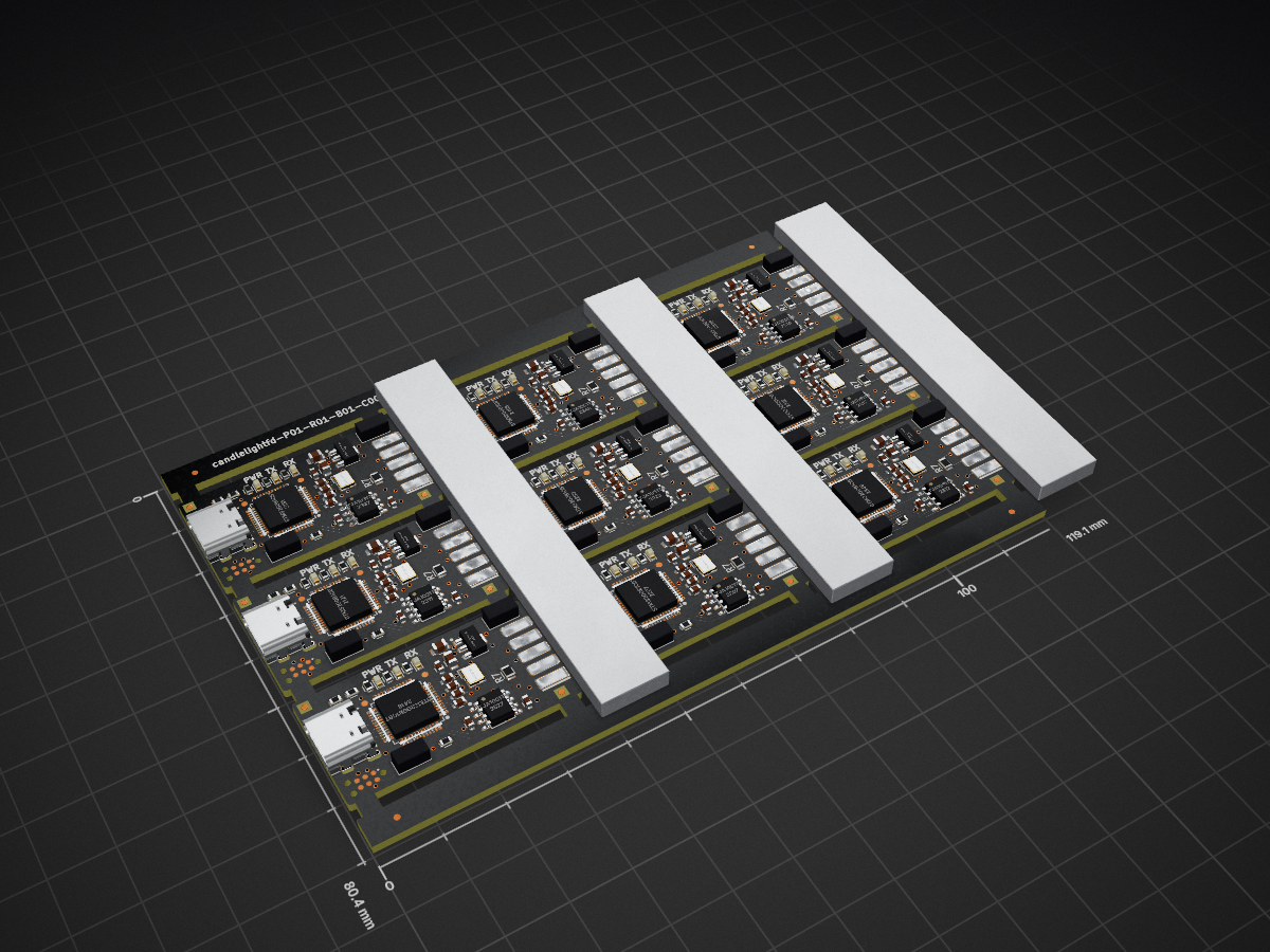
CandleLightfd S01 3x3 is an open-source printed circuit board by linux-automation, from the linux-automation/candleLightFD repository on GitHub. It is a 2-layer board of 119.1 × 80.4 mm with 375 parts on 558 nets, routed with 3,087 tracks and 288 vias.
It is built around the STM32G0B1CBT6, TJA1051T/3 and KPT-1608SGC, with the KPT-1608EC among its other parts. Its parts include 99 capacitors, 72 resistors, 36 ICs, 36 crystals and 27 diodes. It belongs with the STM32 boards of this library.


candleLight FD is a modern, CAN-FD capable version of the candleLight based on a STM32G0B1 microcontroller.
Out of the box it comes with a single CAN channel placed. But footprints for a second CAN channel are available.
The candleLight FD is - like the candleLight - licensed under the CERN OHL v1.2 open hardware license.
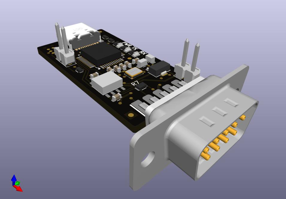
The candleLight FD is available from Linux Automation as a SMD-assembled and functionally tested kit.
The candleLight FD uses a USB-C (USB 2 only) connector to connect to your PC.
CAN is provided on the industry standard D-SUB9 pinout:
Manufacturing Data | Schematic | Interactive BOM
(This is the current release.)
Release Notes:
The firmware is based on the candleLight_fw.
Select the board config BOARD_candleLightFD when building the firmware.
NOTE: We are currently upstreaming our changes to the candleLight_fw repository. While doing so you can find our sources here.
Everyday programming can be done via USB.
Simply invoke dfu-util while the device is running.
More information on flashing can be found in the
firmware repository.
In case the device is bricked: Short the two pins labeled BOOT while powering on the device. The CPU will start in serial download mode.
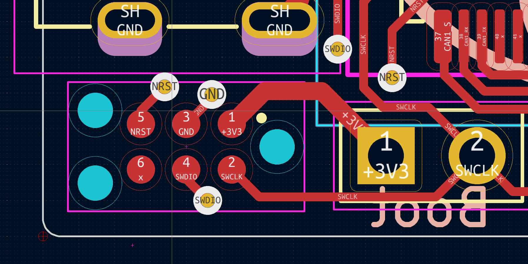
For debugging a single wire interface is exposed on X3. It can be connected using a Tag Connect TC2030-IDC-NL adapter. The pinout is derived from the CandleLight.
The pinout is:
* Pin 1: 3V3
* Pin 2: SWCLK
* Pin 3: GND
* Pin 4: SWDIO
* Pin 5: NRST
* Pin 6: (not connected)
This picture shows X3 on the device. X3 is the connector in the lower left corner - below the USB-C connector.
| Qty | Value | Footprint | References |
|---|---|---|---|
| 36 | 100n_0603_X7R_10%_50V_-40C..125C_Chip-Capacitor | Capacitors_SMD:C_0603 | C10, C10, C10, C10, C10, C10, C10, C10, C10, C11, C11, C11, C11, C11, C11, C11 +20 |
| 27 | 100n | Capacitors_SMD:C_0603 | C3, C3, C3, C3, C3, C3, C3, C3, C3, C4, C4, C4, C4, C4, C4, C4 +11 |
| 27 | 1k_0603_100mW_1%_E24_Chip-Resistor | Resistors_SMD:R_0603 | R3, R3, R3, R3, R3, R3, R3, R3, R3, R4, R4, R4, R4, R4, R4, R4 +11 |
| 27 | TP2.0mm | Connector_generic:TP2.0mm | TP1, TP1, TP1, TP1, TP1, TP1, TP1, TP1, TP1, TP2, TP2, TP2, TP2, TP2, TP2, TP2 +11 |
| 18 | 10u_0805_X7R_10%_10V_-40C..125C_Chip-Capacitor | Capacitors_SMD:C_0805 | C6, C6, C6, C6, C6, C6, C6, C6, C6, C7, C7, C7, C7, C7, C7, C7 +2 |
| 18 | 120R_0805_125mW_1%_E24_Chip-Resistor | Resistors_SMD:R_0805 | R7, R7, R7, R7, R7, R7, R7, R7, R7, R8, R8, R8, R8, R8, R8, R8 +2 |
| 18 | 5k1_0603_100mW_1%_E24_Chip-Resistor | Resistors_SMD:R_0603 | R1, R1, R1, R1, R1, R1, R1, R1, R1, R2, R2, R2, R2, R2, R2, R2 +2 |
| 18 | 6p2_0603_C0G_5%_50V_-40C..125C_Chip-Capacitor | Capacitors_SMD:C_0603 | C1, C1, C1, C1, C1, C1, C1, C1, C1, C2, C2, C2, C2, C2, C2, C2 +2 |
| 18 | CONN_01X02 | Connector_generic:Header_1x2_Pitch2.54mm | P1, P1, P1, P1, P1, P1, P1, P1, P1, P2, P2, P2, P2, P2, P2, P2 +2 |
| 18 | KPT-1608SGC | LEDs_Kingbright:LED_Kingbright_0603 | D1, D1, D1, D1, D1, D1, D1, D1, D1, D2, D2, D2, D2, D2, D2, D2 +2 |
| 18 | Passermarke_1mm_1.8mmx1.8mm | mechanical:Passermarke_1mm_1.8mmx1.8mm | NB3, NB3, NB3, NB3, NB3, NB3, NB3, NB3, NB3, NB4, NB4, NB4, NB4, NB4, NB4, NB4 +2 |
| 18 | TJA1051T3 | tssop:SOIC-8_3.90mmx4.90mm_Pitch1.27mm | U3, U3, U3, U3, U3, U3, U3, U3, U3, U4, U4, U4, U4, U4, U4, U4 +2 |
| 18 | TP1.0mm | Connector_generic:TP1.0mm | TP4, TP4, TP4, TP4, TP4, TP4, TP4, TP4, TP4, TP5, TP5, TP5, TP5, TP5, TP5, TP5 +2 |
| 9 | 10k_0603_100mW_1%_E24_Chip-Resistor | Resistors_SMD:R_0603 | R6, R6, R6, R6, R6, R6, R6, R6, R6 |
| 9 | 629722000214_pasteInHole | Socket_GCT:USB4105_pasteInHole | X1, X1, X1, X1, X1, X1, X1, X1, X1 |
| 9 | 830055299 | crystal:Crystal_4Pin_SMD_3.2mmx2.5mm | Y1, Y1, Y1, Y1, Y1, Y1, Y1, Y1, Y1 |
| 9 | KPT-1608EC | LEDs_Kingbright:LED_Kingbright_0603 | D3, D3, D3, D3, D3, D3, D3, D3, D3 |
| 9 | LAG_Rocket | mechanical:lag_rocket_14.5mmx15mm | NB1, NB1, NB1, NB1, NB1, NB1, NB1, NB1, NB1 |
| 9 | LAYERSTACK_TB | mechanical:LAYERSTACK_TB | NB2, NB2, NB2, NB2, NB2, NB2, NB2, NB2, NB2 |
| 9 | MCP1754ST-3302E/MB | TO_SMD:SOT-89 | U2, U2, U2, U2, U2, U2, U2, U2, U2 |
| 9 | STM32G0B1CBT | QFP:LQFP-48_7mmx7mm_Pitch0.5mm | U1, U1, U1, U1, U1, U1, U1, U1, U1 |
| 9 | TC2030-NL | Connector_Tag-Connect:TC2030-NL | X3, X3, X3, X3, X3, X3, X3, X3, X3 |
| 9 | ~ | d-sub:D-SUB-9_side | X2, X2, X2, X2, X2, X2, X2, X2, X2 |
The 369 most common of 375 parts.
linux-automation/candleLightFD
USB CAN-FD interface based on the STM32G0 that works well with gs_usb on Linux

fake-name/cfs-reverse-engineering
Reverse engineering the Creality CFS for use as a general AMU/MMU system

bluesatunsw/owr
This repo includes all software necessary to operate the Test Rover Platform that is being designed and developed in the 502 project.

Prajwal-sahyadri-ECE/-Optimized-Powersupply-design-
A highly detailed PCB to maintain an power supply for a defined hardware architecture specifically for ICS system

PranavNedunghat/Jetson-Carrier-PX4-Fusion-
This project contains open hardware design files for a baseboard supporting the NVIDIA Jetson Nano, Xavier NX and TX2 NX SoMs.


dhruxraj/stm32-can-ecu
A compact, "ECU-style" CAN node for learning and prototyping automotive-type embedded software. It has an STM32G4 MCU, a CAN transceiver with protection and switchable termination, a 6-axis IMU, a protected 8-18 V…

PurkkaKoodari/ktane-hw
Fully playable hardware implementation of Keep Talking and Nobody Explodes. Mirror of https://gitlab.com/PurkkaKoodari/ktane-hw

It measures 119.1 × 80.4 mm and has 2 copper layers, 1.6 mm thick.
375 parts, built around the STM32G0B1CBT6, TJA1051T/3, KPT-1608SGC and KPT-1608EC. The full list of its parts is on this page, with links to each part's symbol and footprint where PCBKit's library has them.
From the linux-automation/candleLightFD repository on GitHub, at the commit this page was made from: the board is release/candlelightfd-S01-R01/candlelightfd-P01-R01-V01/panel_3x3/candleLightfd-S01_3x3.kicad_pcb and its schematic MCU.kicad_sch. PCBKit opens the board in the browser, with nothing to install.
Its repository states no licence, so its author keeps all rights: ask linux-automation before reusing the design.