
2 layers27 × 177 mm
Bookmark
DaringCuteSeal/spinetime
A neurodivergent-friendly linear clock gadget for time management in binder journals.
53 parts3

 DaringCuteSeal/spinetime3
A neurodivergent-friendly linear clock gadget for time management in binder journals.
Controller is an open-source printed circuit board by DaringCuteSeal, from the DaringCuteSeal/spinetime repository on GitHub. It is a 2-layer board of 52 × 29 mm with 42 parts on 40 nets, routed with 305 tracks and 35 vias.
It is built around the ATTINY1616-MN, DS3231S# and TP4056, with the 1SS404 and DMP1045U among its other parts. Its parts include 17 resistors, 6 capacitors, 5 diodes, 4 ICs and 4 connectors. It belongs with the lEDs and displays boards and the AVR (ATmega, ATtiny) boards of this library.


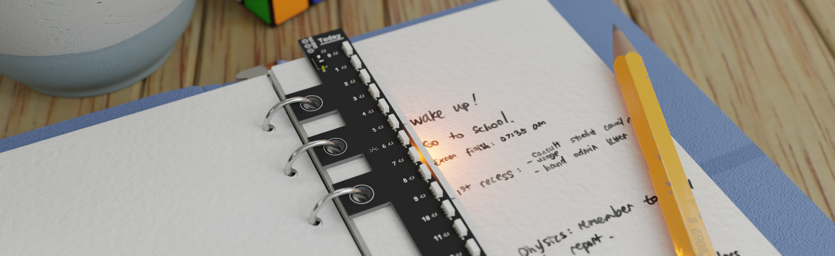
Spinetime is a ring binder-integrated linear clock 1 designed to help students and neurodivergent individuals manage time and tasks more effectively. Users of Spinetime can visualize the passage of the day at a glance, providing aid especially for those who struggle with time blindness.
It is surprising to me that people have manufactured papers with time table template, but not invent something as simple as a pointer that tells you how far you have gone through your table. I suspect that this is because most people do not experience time blindness, and having some kind of pointer of the table isn't really all that useful. This is simply not the case for those with time blindness: time doesn't really mean anything if presented in the wrong way. I hope that the proof of concept that came with Spinetime may help present time meaningfully for those who struggle with time blindness like me.
As someone who suffers from time blindness on a daily basis, I find managing my time extremely challenging. It's been intensely hard to picture how I'll spend my time for a particular day. Having shuffled between multiple time management methods, I constantly find myself at home when I plan my day out on my physical journal. I simply love the tactile feel of using a physical tool to plan out my day.
However, being the visual-oriented person I am, lacking any visual cue of "where" in the time dimension I am at any given day has been a major deal-breaker that has kept me from using physical tools for journalling. Of course, journalling papers with pre-made time tables exist, but they don't tell me what time it really is right now in any tangible manner relating to the table itself—what a bummer.
I've been using ChronoCat (not affiliated) to manage my time lately, and it's been a perfect digital tool—minimalistic, very visual, and easy to use. It provides the user with a time table alongside a visual cue of where they are within the day. However, like I said before, I crave the tactile feel of physical note-taking. It'd also be great if I can plan my day without the distraction that comes with using a full-fledged mobile phone or computer. Plus, being able to plan my day at school would be a great2. I always dream that one day, I won't forget several of my appointments again.
I looked at my own journalling book again, and thought: you know, I think that ChronoCat's approach doesn't have to be in the form of a digital app. And so, I came up with SpineTime.
Daily use: simply strap Spinetime to your ring binder by opening the spine and inserting the linear clock component and start annotating your day. This repository hosts the A6 binder-compatible version.
How to charge the battery: charge with a type-C cable. 5V, obviously. The controller implements load sharing so you'll be powering the circuit directly with the given 5V when charged.
The LEDs of the bookmark are controlled by a separate controller unit. An ATtiny1616 MCU is used alongside a DS3231 RTC.
You will need:
Steps:
SET_TIME to true in the cfg.h file first to set time, then flash again with SET_TIME set to false. You will need a USB-to-TTL adapter. Connect the TX pin of the adapter to the TX pin of SpineTime's controller PCB and the RX pin of the adapter to RX. Note that the PCB doesn't have labels for that.. just check the kicad file to know which is which :P. Then, connect the adapter's ground accordingly.Gotchas:
Spinetime, SpineTime, spinetime are all valid. No spineTime or spine_time or anything else.
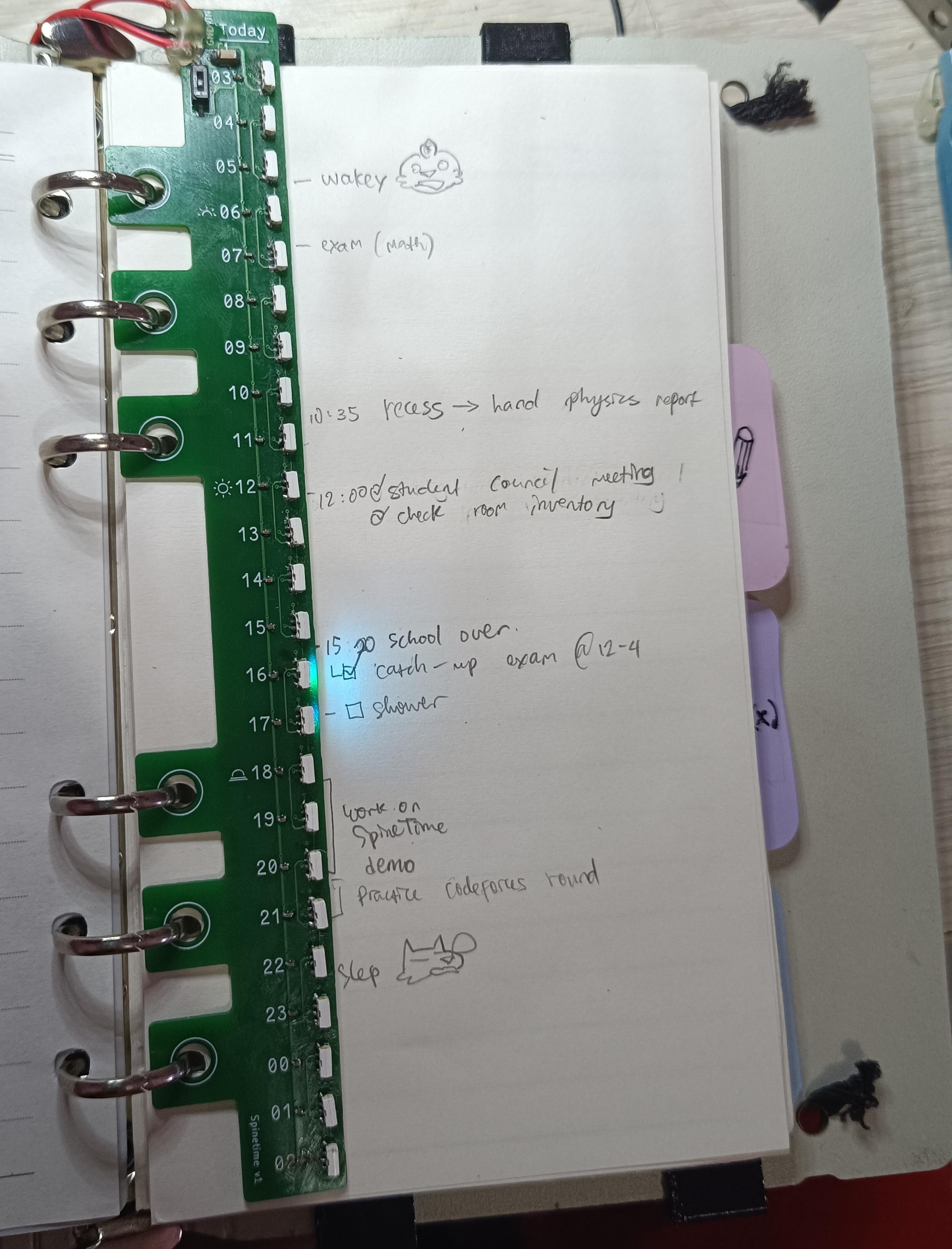
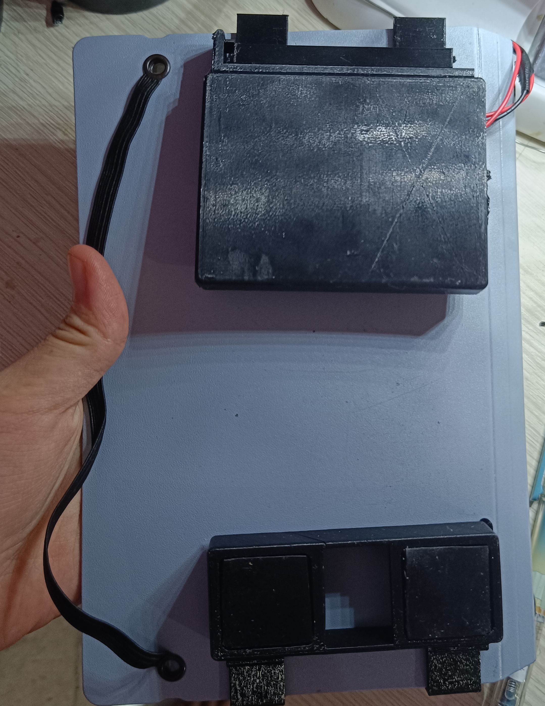
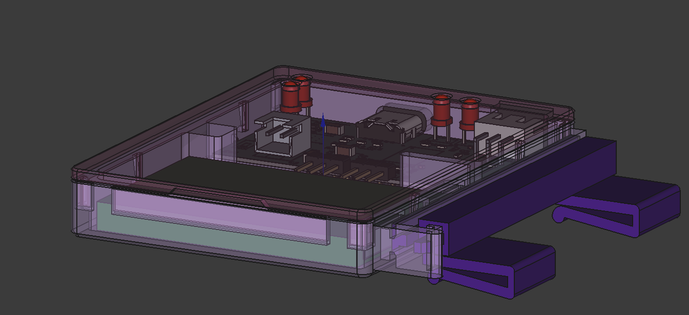
Note: I built it with LEDs too big so I didn't put on the casing lid.
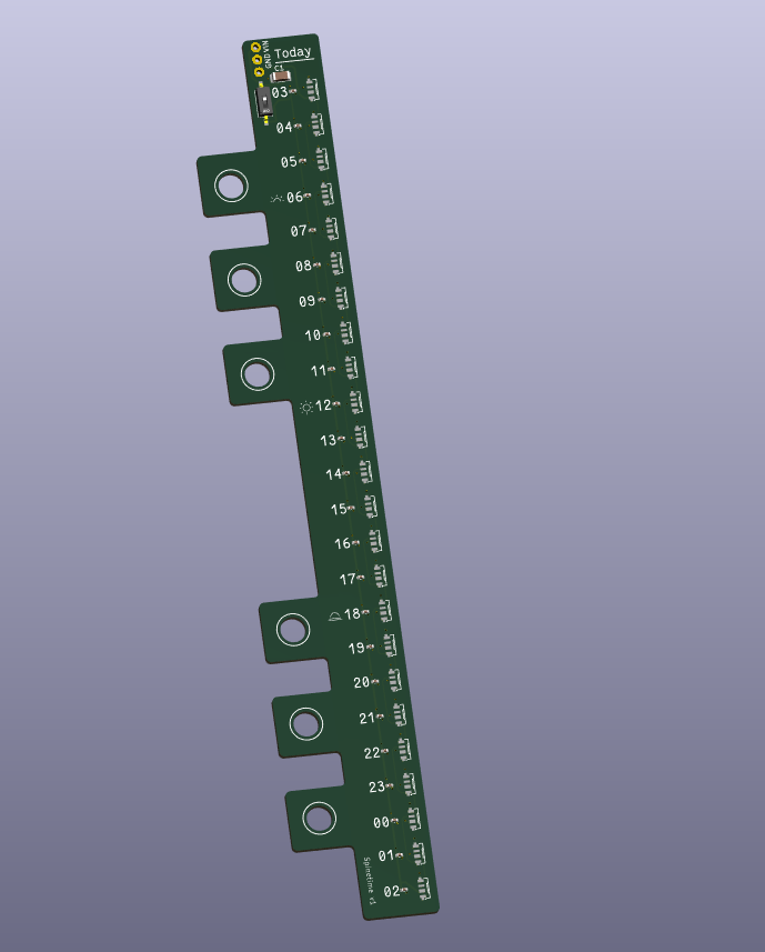
The actual bookmark (project files, .step file):
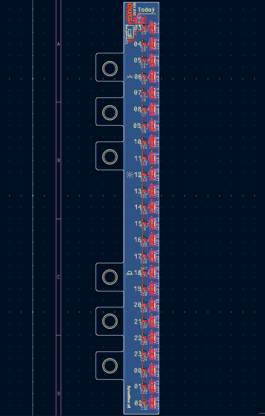
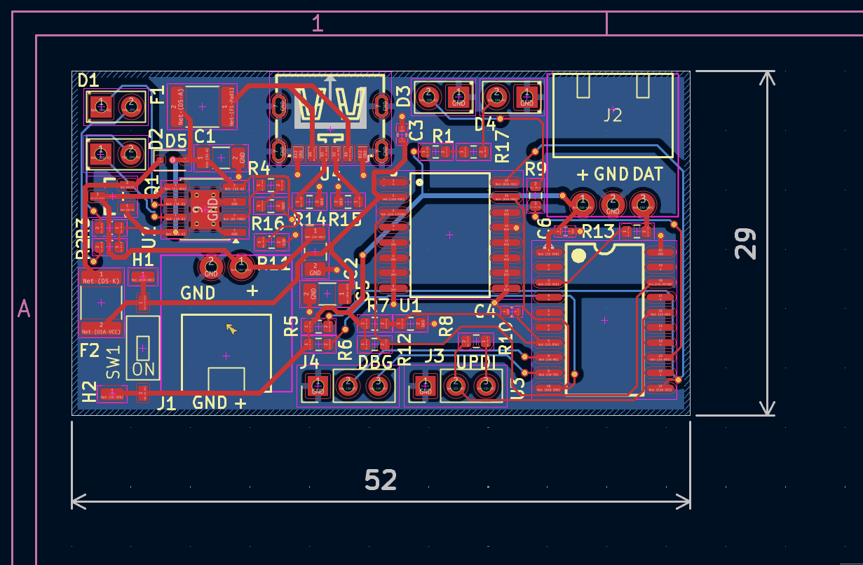
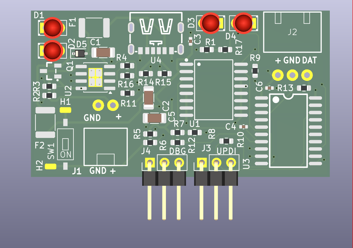
The controller unit (project files, .step file):
Schematics:
The model files can be found under freecad/.
Casing:
Support clip (so your book cover won't wobble when being written on):
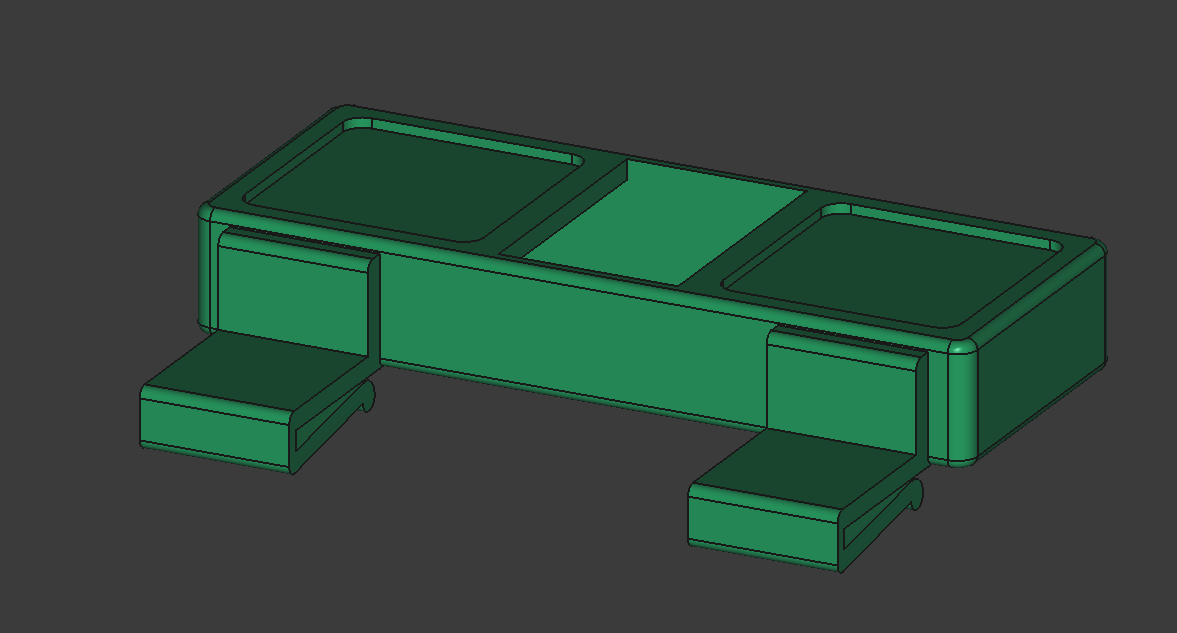
The firmware files for SpineTime, spinetime-fw, can be found in the firmware directory.
BOM/bill of materials for this project can be found here.
Thanks to Hack Club for supporting! Initially made for Hack Club Blueprint, but later got transferred to Hack Club Fallout.
Awesome software used:
Awesome services used:
I used several 3D models for my PCB 3D model:
References (unfortunately not all, just the very notable ones):
Huh, am I over-crediting? maybe..
I used ChatGPT for sanity-checking my configurations (including my controller schematic, for instance it caught that I didn't pull the CC pins to ground).
| Qty | Value | Footprint | References |
|---|---|---|---|
| 8 | 1K | Resistor_SMD:R_0603_1608Metric | R1, R2, R3, R4, R9, R10, R16, R17 |
| 3 | 0.1u | Capacitor_SMD:C_0402_1005Metric | C3, C4, C6 |
| 3 | 100u | Capacitor_SMD:C_1206_3216Metric | C1, C2, C5 |
| 3 | 10K | Resistor_SMD:R_0603_1608Metric | R5, R6, R12 |
| 2 | 5K1 | Resistor_SMD:R_0603_1608Metric | R14, R15 |
| 1 | 100K | Resistor_SMD:R_0603_1608Metric | R11 |
| 1 | 1M | Resistor_SMD:R_0603_1608Metric | R7 |
| 1 | 1SS404 | Diode_SMD:D_SOD-323 | D5 |
| 1 | 200m | Fuse:Fuse_1812_4532Metric | F2 |
| 1 | 255K | Resistor_SMD:R_0603_1608Metric | R8 |
| 1 | 330 | Resistor_SMD:R_0603_1608Metric | R13 |
| 1 | 750m | Fuse:Fuse_1812_4532Metric | F1 |
| 1 | ATTINY1616 | custom-footprints:SOIC-20_L12.8-W7.5-P1.27-LS10.3-BL | U3 |
| 1 | CONN_UPDI | Connector_PinHeader_2.54mm:PinHeader_1x03_P2.54mm_Vertical | J3 |
| 1 | DMP1045U | custom-footprints:SOT-23-3_L2.9-W1.5-P1.90-LS2.6-BR | Q1 |
| 1 | DS3231 | custom-footprints:SOIC-16_L10.3-W7.5-P1.27-LS10.3-BL | U1 |
| 1 | JST_BAT | custom-footprints:JST_1x2_2.54mm-horizontal_1 | J1 |
| 1 | JST_BOOKMARK | custom-footprints:JST_1x3_2.54mm-horizontal | J2 |
| 1 | LED_R | LED_THT:LED_D2.0mm_W4.8mm_H2.5mm_FlatTop | D2 |
| 1 | LED_R_IND. | LED_THT:LED_D2.0mm_W4.8mm_H2.5mm_FlatTop | D4 |
| 1 | LED_R_LO | LED_THT:LED_D2.0mm_W4.8mm_H2.5mm_FlatTop | D3 |
| 1 | LED_Y | LED_THT:LED_D2.0mm_W4.8mm_H2.5mm_FlatTop | D1 |
| 1 | PERPH_VIN_DBG | Connector_Wire:SolderWirePad_1x01_SMD_1x2mm | H2 |
| 1 | SW_DIP_x01 | custom-footprints:SW-SMD_CHS-01B | SW1 |
| 1 | TP4056 | Package_SO:SOIC-8-1EP_3.9x4.9mm_P1.27mm_EP2.41x3.3mm_ThermalVias | U2 |
| 1 | UART_DBG | Connector_PinHeader_2.54mm:PinHeader_1x03_P2.54mm_Vertical | J4 |
| 1 | VIN_DBG | Connector_Wire:SolderWirePad_1x01_SMD_1x2mm | H1 |
| 1 | ~ | custom-footprints:USB-C-SMD_USB-TYPE-C-006 | U4 |
It measures 52 × 29 mm and has 2 copper layers, 0.8 mm thick.
42 parts, built around the ATTINY1616-MN, DS3231S#, TP4056 and 1SS404. The full list of its parts is on this page, with links to each part's symbol and footprint where PCBKit's library has them.
From the DaringCuteSeal/spinetime repository on GitHub, at the commit this page was made from: the board is kicad/controller/controller.kicad_pcb and its schematic kicad/bookmark/controller_board.kicad_sch. PCBKit opens the board in the browser, with nothing to install.
Its repository states no licence, so its author keeps all rights: ask DaringCuteSeal before reusing the design.
DaringCuteSeal/spinetime
A neurodivergent-friendly linear clock gadget for time management in binder journals.


vmfachini/Lumibot
Desenvolvimento de um Hardware Livre, com uso de energia limpa, baseado no micro:bit para criar robôs móveis acessíveis, promovendo ensino de robótica, pensamento computacional e sustentabilidade no Brasil.

NikolaiRadke/Noko_2
The do-it-yourself Arduino-based Noko monster. Version 2 with PCB and 3D printed casing.

Ezerwald/stm32-kicad-weather-station
KiCad-based PCB project for an STM32-powered IoT weather station with environmental sensing, real-time clock support, battery charging, and e-paper display connectivity.

wabolabs/autofeedermod
ESP32-C6 based chicken feed dispenser controller with Matter, CAN bus, and 18650 battery

