2 layers350 × 224.3 mm

 danwerner21/TI99_2250
a 2022 replica of the classic TI/994a, using obtainable parts
Keyboard is an open-source printed circuit board by danwerner21, from the danwerner21/TI99_22 repository on GitHub. It is a 2-layer board of 282.7 × 108.3 mm with 63 parts on 34 nets, routed with 390 tracks and 8 vias.
It is built around the ATTINY13A-PU and 74LS125DC. Its parts include 48 switches, 3 resistors, 2 ICs, 2 diodes and 1 capacitor. It belongs with the keyboards and input boards and the AVR (ATmega, ATtiny) boards of this library.

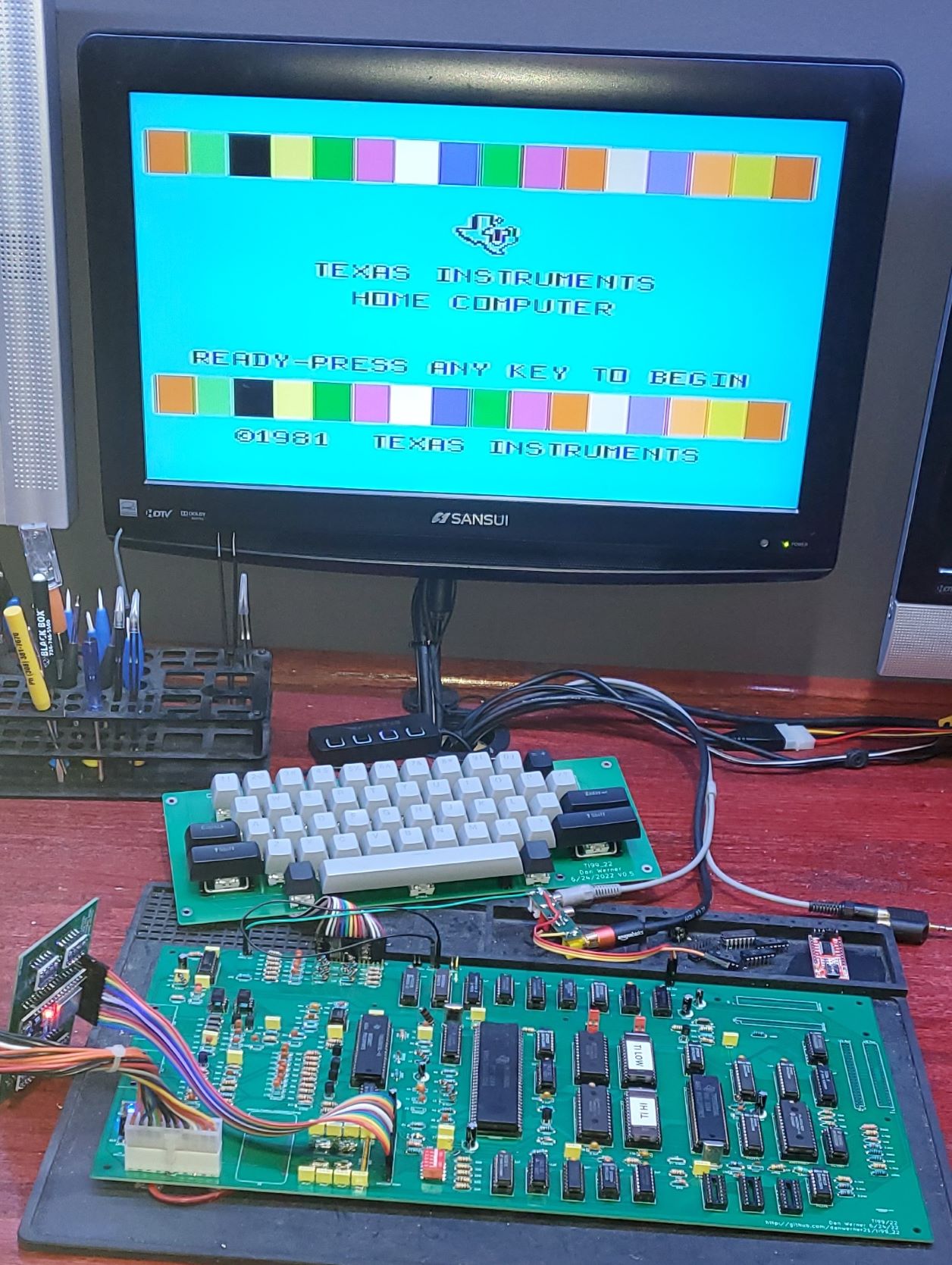
Note that this is not a fully tested project at this point. . . .
This is based Rob Krenicki's design that is based on the HackMac KiCAD schematics. I have made several changes to the original design including:
If there are any questions, I can be reached at vic2020Dan at gmail dot com.
Cleanup/Documentation Possible Future Thoughts:
Redo the Board in an ATX form factor with PEB slots on board
Add Support for the Pico9918 on-board
Add Support for a Tang Nano FPGA TMS9918 replacement
Add Hex-bus port
Add a DIN 5-pin Composite video/Audio out.
Add built in speech synthesis
Clone Disk IO card
Relocate all the ports to the back of the motherboard
It has been suggested that we also have a console style version of the next revision as not everyone has a desire for a larger PE style machine
Also perhaps add some keys to the keyboard
The DIP switch on the main board allows one to configure which bank areas are populated with RAM.
RAM0 enables RAM to addresses >2000-3FFF (Lo Memory Expansion) RAM1 enables RAM to addresses >A000-BFFF (Hi Memory Expansion) RAM2 enables RAM to addresses >C000-DFFF (Hi Memory Expansion) RAM3 enables RAM to addresses >E000-FFFF (Hi Memory Expansion) RAM4 enables RAM to addresses >8000-83FF (Normal TI Scratch Pad RAM)
Note that I have never actually tested off-board 8 bit RAM, so this is new territory and might need some debugging 😊
also on-board RAM is 16 bit – so all of those external RAM sources will be slower.
on rev 0.95 R36-40 are listed as 100K ohm, they are actually 100 ohm
on rev 0.95 the joystick and cassette connectors are mirrored and need to be mounted on the bottom side of the board to function
Both of these are corrected in 0.96
The reset button J1 should be attached to pin 5 of U1 not Pin 4
| Qty | Reference(s) | Part |
|---|---|---|
| 6 | C1, C9, C11, C58, C73, C75 | 0.001uF |
| 1 | C2 | 22pF |
| 3 | C3, C5, C59 | 22uF |
| 12 | C4, C7, C13, C14, C20, C54, C55, C62, C64, C68, C71, C74 | 0.1uF |
| 1 | C6 | 1uF |
| 7 | C8, C52, C63, C65, C66, C67, C72 | 0.01uF |
| 1 | C10 | 100uF |
| 1 | C12 | 0.01uF |
| 7 | C15, C16, C17, C19, C21, C22, C60 | 100uF |
| 30 | C18, C23, C24, C25, C26, C27, C28, C29, C30, C31, C32, C33, C34, C35, C36, C37, C38, C39, C40, C41, C42, C43, C44, C45, C46, C47, C48, C49, C50, C51 | 0.1uF |
| 1 | C53 | 100uF |
| 1 | C56 | 12pF |
| 1 | C57 | 56pF |
| 1 | C61 | 220uF |
| 1 | C69 | 220pF |
| 1 | C70 | 0.022uF |
| 2 | CR1, CR4 | 1N4148 |
| 2 | CR2, CR3 | 1N914B |
| 1 | D1 | LED |
| 1 | J1 | Connector PinHeader 2.54mm:PinHeader 1x02 P2.54mm Vertical |
| 1 | J2 | Connector PinHeader 2.54mm:PinHeader 1x02 P2.54mm Vertical |
| 1 | J3 | TerminalBlock RND:TerminalBlock RND 205-00278 1x04 P5.00mm Vertical |
| 1 | J4 | Connector PinHeader 2.54mm:PinHeader 1x16 P2.54mm Vertical |
| 2 | J5, J6 | Connector PinHeader 2.54mm:PinHeader 1x03 P2.54mm Vertical |
| 1 | J7 | Connector PinHeader 2.54mm:PinHeader 1x03 P2.54mm Vertical |
| 1 | J8 | Connector PinHeader 2.54mm:PinHeader 1x02 P2.54mm Vertical |
| 1 | J9 | Connector PinHeader 2.54mm:PinHeader 1x02 P2.54mm Vertical |
| 1 | J10 | Connector Dsub:DSUB-9 Female Horizontal P2.77x2.84mm EdgePinOffset4.94mm Housed MountingHolesOffset7.48mm |
| 1 | J11 | Connector PinHeader 2.54mm:PinHeader 1x18 P2.54mm Vertical |
| 1 | J12 | Connector PinHeader 2.54mm:PinHeader 2x22 P2.54mm Vertical |
| 1 | J13 | WernerCustomLibrary:44 Pin Card Edge |
| 1 | J14 | Library:CardEdge 34Pin 2.54mm Vertical |
| 1 | J15 | Connector PinHeader 2.54mm:PinHeader 2x18 P2.54mm Vertical |
| 1 | J16 | Connector PinSocket 2.54mm:PinSocket 1x03 P2.54mm Vertical |
| 1 | J17 | Connector PinSocket 2.54mm:PinSocket 1x03 P2.54mm Vertical |
| 1 | J18 | Connector Dsub:DSUB-9 Female Horizontal P2.77x2.84mm EdgePinOffset4.94mm Housed MountingHolesOffset7.48mm |
| 1 | L1 | 0.33uH |
| 2 | L4, L5 | 6.8uH |
| 1 | L7 | 5.8uH |
| 1 | L8 | INDUCTOR (Ferrite BEAD) |
| 7 | L10, L11, L12, L13, L14, L15, L16 | 8.2uH |
| 3 | Q1, Q3, Q4 | TIS92 |
| 1 | Q2 | 2N3904 |
| 1 | R1 | 150k |
| 7 | R2, R9, R11, R18, R34, R35, R46 | 1k |
| 1 | R3 | 12k |
| 1 | R4 | 47k |
| 4 | R5, R6, R7, R8 | 22 |
| 5 | R10, R26, R45, R52, R53 | 4.7k |
| 5 | R12, R13, R14, R15, R16 | 1K |
| 3 | R17, R48, R50 | 2.2k |
| 2 | R19, R30 | 470 |
| 1 | R20 | 270 |
| 1 | R21 | 1.5k x 9 SIP bussed |
| 1 | R22 | 361 |
| 3 | R23, R73, R75 | 5.6k |
| 2 | R24, R27 | 10 |
| 1 | R25 | 150 |
| 1 | R28 | 470k |
| 1 | R29 | 0 |
| 2 | R31, R33 | 75 |
| 1 | R32 | 470 |
| 4 | R41, R42, R43, R44 | 62 |
| 1 | R47 | 3.3k |
| 9 | R36, R37, R38, R39, R40, R49, R51, R54, R56 | 100 |
| 1 | R55 | 330 |
| 1 | R57 | 10k |
| 1 | R58 | 6.8k |
| 1 | R59 | 39k |
| 1 | R60 | 6.8k |
| 4 | R61, R62, R67, R68 | 1K |
| 1 | R63 | 120k |
| 1 | R64 | 2.7k |
| 3 | R65, R66, R76 | 220 |
| 1 | R69 | 10K |
| 1 | R70 | 9.1k |
| 2 | R71, R72 | 10k |
| 1 | R74 | 5.6K |
| 1 | R77 | 15 |
| 2 | RN1, RN2 | 10K x 9 SIP Bussed |
| 1 | SW1 | DIP switchx05 |
| 1 | SW2 | Pin Header 01x02 Male |
| 1 | U1 | TMS9904 (note this needs to be a 9904 not 9904ANL. If the 9904ANL is used, Y1 needs to be substituted with 12Mhz, L1 needs to be substituted with 3.3uh and C2 needs to be substituted with 50pf) |
| 1 | U2 | TMS9900 |
| 4 | U3, U15, U22, U24 | 74LS04 |
| 2 | U4, U9 | 74LS32 |
| 2 | U5, U8 | 74LS138 |
| 1 | U6 | 74LS03 |
| 1 | U7 | 74LS08 |
| 3 | U10, U14, U18 | 74LS00 |
| 2 | U11, U41 | 74LS244 |
| 1 | U12 | 74LS373 |
| 1 | U13 | 74LS245 |
| 1 | U16 | 74LS74 |
| 1 | U17 | 74LS194 |
| 1 | U19 | LM2901 |
| 1 | U20 | LM7905 TO220 |
| 1 | U21 | LM2903 |
| 3 | U26, U27, U28 | TMC0430 |
| 3 | U29, U30, U37 | HM62256BLP |
| 2 | U31, U32 | 27C64 |
| 1 | U33 | SN76489 |
| 1 | U34 | TMS9918 |
| 3 | U35, U36, U38 | 74LS574 |
| 1 | U39 | TMS9901 |
| 1 | U40 | 74LS156 |
| 2 | U42, U43 | 74LS367 |
| 1 | U44 | 74LS379 |
| 1 | U45 | 27C010 |
| 1 | U46 | RC4558 |
| 1 | U47 | 74LS06 |
| 2 | U48, U49 | TIL119 |
| 1 | Y1 | 48.000 MHz Crystal |
| 1 | Y2 | 10.7MHz Crystal |
| Qty | Reference(s) | Value | Part |
|---|---|---|---|
| 1 | C1 | 0.1uF | Capacitor |
| 1 | D1 | LED | LED |
| 1 | D2 | LED | LED |
| 1 | J1 | Pin Header 1x18 male | Pin Header 1x18 male |
| 2 | R1, R2 | 470 ohm | Resistor |
| 1 | R3 | 1K ohm | Resistor |
| 48 | SW1-SW48 | Mechanical Switch | Cherry MX Switch (or compatible) |
| 1 | U1 | ATtiny13A-P | IC |
| 1 | U2 | 74LS125 | IC |
| 3 | Switch Stabilizer 2.25 | ||
| 1 | Switch Stabilizer 6.25 | ||
| 1 | Optional Alignment frame (will need modified) | ||
| Stabilizers (frame not used): | https://www.amazon.com/Genuine-Cherry-PCB-Snap-Stabilizers/dp/B085T8QZJC | ||
| Stabilizers (Frame used) | https://www.amazon.com/dp/B082X4V9VC | ||
| Frame: | https://www.amazon.com/gp/product/B07MMB33WG |
| Qty | Reference(s) | Part | Type |
|---|---|---|---|
| 1 | J1 | Pin Header 01x18 Male | Pin Header 01x18 Male |
| 1 | J2 | 36 Pin Edge Connector | CONN EDGE DUAL FMALE 36POS 0.100 spacing |
| Qty | Reference(s) | Part | Type |
|---|---|---|---|
| 1 | J1 | Pin Header 2x22 Male | Pin Header 2x22 Male |
| Qty | Reference(s) | Part | Type |
|---|---|---|---|
| 1 | J1 | Pin Header Socket 01x16 Female Right Angle | Pin Header Socket 01x16 Female Right Angle |
| 4 | U1-U4 | Level Shifter | https://www.amazon.com/KeeYees-Channels-Converter-Bi-Directional-Shifter/dp/B07LG646VS |
| 1 | U5 | ESP32 Devkit | https://www.amazon.com/Development-Microcontroller-Integrated-Antenna-Amplifiers/dp/B09GK74F7N |
The original project was licensed under the Creative Commons - Attribution - ShareAlike 3.0 License
This board was derrived from works by, uses design elements from, or contains sofware writen by the following:
| Qty | Value | Footprint | References |
|---|---|---|---|
| 6 | MountingHole | MountingHole:MountingHole_3.2mm_M3_Pad | H1, H2, H3, H4, H5, H6 |
| 2 | 470Ω | Resistor_THT:R_Axial_DIN0207_L6.3mm_D2.5mm_P7.62mm_Horizontal | R1, R2 |
| 1 | 0 | Cherry_MX:CHERRY_PCB_100H | SW19 |
| 1 | 0.1µF | Capacitor_THT:C_Disc_D7.0mm_W2.5mm_P5.00mm | C1 |
| 1 | 1 | Cherry_MX:CHERRY_PCB_100H | SW43 |
| 1 | 1KΩ | Resistor_THT:R_Axial_DIN0207_L6.3mm_D2.5mm_P7.62mm_Horizontal | R3 |
| 1 | 2 | Cherry_MX:CHERRY_PCB_100H | SW44 |
| 1 | 3 | Cherry_MX:CHERRY_PCB_100H | SW45 |
| 1 | 4 | Cherry_MX:CHERRY_PCB_100H | SW46 |
| 1 | 5 | Cherry_MX:CHERRY_PCB_100H | SW47 |
| 1 | 6 | Cherry_MX:CHERRY_PCB_100H | SW23 |
| 1 | 7 | Cherry_MX:CHERRY_PCB_100H | SW22 |
| 1 | 74LS125 | Package_DIP:DIP-14_W7.62mm_Socket_LongPads | U2 |
| 1 | 8 | Cherry_MX:CHERRY_PCB_100H | SW21 |
| 1 | 9 | Cherry_MX:CHERRY_PCB_100H | SW20 |
| 1 | A | Cherry_MX:CHERRY_PCB_100H | SW30 |
| 1 | ATtiny13A-P | Package_DIP:DIP-8_W7.62mm_LongPads | U1 |
| 1 | Alpha | LED_THT:LED_D3.0mm | D1 |
| 1 | B | Cherry_MX:CHERRY_PCB_100H | SW28 |
| 1 | C | Cherry_MX:CHERRY_PCB_100H | SW26 |
| 1 | COLON | Cherry_MX:CHERRY_PCB_100H | SW7 |
| 1 | COMMA | Cherry_MX:CHERRY_PCB_100H | SW3 |
| 1 | CTRL | Button_Switch_Keyboard:SW_Cherry_MX_1.25u_PCB | SW42 |
| 1 | Computer | Connector_PinHeader_2.54mm:PinHeader_1x18_P2.54mm_Vertical | J1 |
| 1 | D | Cherry_MX:CHERRY_PCB_100H | SW32 |
| 1 | E | Cherry_MX:CHERRY_PCB_100H | SW39 |
| 1 | ENTER | Cherry_MX:CHERRY_PCB_225H | SW18 |
| 1 | EQUALS | Cherry_MX:CHERRY_PCB_100H | SW6 |
| 1 | F | Cherry_MX:CHERRY_PCB_100H | SW33 |
| 1 | FNCT | Button_Switch_Keyboard:SW_Cherry_MX_1.25u_PCB | SW48 |
| 1 | G | Cherry_MX:CHERRY_PCB_100H | SW34 |
| 1 | H | Cherry_MX:CHERRY_PCB_100H | SW11 |
| 1 | I | Cherry_MX:CHERRY_PCB_100H | SW15 |
| 1 | J | Cherry_MX:CHERRY_PCB_100H | SW10 |
| 1 | K | Cherry_MX:CHERRY_PCB_100H | SW9 |
| 1 | L | Cherry_MX:CHERRY_PCB_100H | SW8 |
| 1 | LOCK | Button_Switch_Keyboard:SW_Cherry_MX_1.75u_PCB | SW29 |
| 1 | M | Cherry_MX:CHERRY_PCB_100H | SW4 |
| 1 | N | Cherry_MX:CHERRY_PCB_100H | SW5 |
| 1 | O | Cherry_MX:CHERRY_PCB_100H | SW14 |
| 1 | P | Cherry_MX:CHERRY_PCB_100H | SW13 |
| 1 | PERIOD | Cherry_MX:CHERRY_PCB_100H | SW2 |
| 1 | Power | LED_THT:LED_D3.0mm | D2 |
| 1 | Q | Cherry_MX:CHERRY_PCB_100H | SW37 |
| 1 | R | Cherry_MX:CHERRY_PCB_100H | SW40 |
| 1 | S | Cherry_MX:CHERRY_PCB_100H | SW31 |
| 1 | SHIFT | Cherry_MX:CHERRY_PCB_275H | SW35 |
| 1 | SHIFT | Cherry_MX:CHERRY_PCB_225H | SW36 |
| 1 | SLASH | Cherry_MX:CHERRY_PCB_100H | SW1 |
| 1 | SPACE | Cherry_MX:CHERRY_PCB_625H | SW12 |
| 1 | T | Cherry_MX:CHERRY_PCB_100H | SW41 |
| 1 | U | Cherry_MX:CHERRY_PCB_100H | SW16 |
| 1 | V | Cherry_MX:CHERRY_PCB_100H | SW27 |
| 1 | W | Cherry_MX:CHERRY_PCB_100H | SW38 |
| 1 | X | Cherry_MX:CHERRY_PCB_100H | SW25 |
| 1 | Y | Cherry_MX:CHERRY_PCB_100H | SW17 |
| 1 | Z | Cherry_MX:CHERRY_PCB_100H | SW24 |


emeargt/nes-cnrom
KiCad project for NES-CN-ROM-256-05 cartridge schematic and PCB

digilogistist/The-Open-Source-USB-NES-Project
USB-NES and NES-FASTGFX product engineering repository


WiiMake/picones
In the last 40 years, technology has advanced to the point were what used to be done in hardware can now be done in software. This project uses an rp2350 to emulate a ROM chip on an NES Cartridge.


bazsimarkus/a277d-led-tachometer
An analog LED tachometer controlled by an East German A277D chip (clone of UAA180), featuring an integrated ATtiny13A-based digital ignition pulse generator for testing.
It measures 282.7 × 108.3 mm and has 2 copper layers, 1.6 mm thick.
63 parts, built around the ATTINY13A-PU and 74LS125DC. The full list of its parts is on this page, with links to each part's symbol and footprint where PCBKit's library has them.
From the danwerner21/TI99_22 repository on GitHub, at the commit this page was made from: the board is Keyboard/Keyboard.kicad_pcb and its schematic CartRiser/CartRiser/CartRiser.kicad_sch. PCBKit opens the board in the browser, with nothing to install.
Its repository states no licence, so its author keeps all rights: ask danwerner21 before reusing the design.