
4 layers39 × 39 mm
OneInchEye
will127534/OneInchEye
A One Inch CMOS sensor (IMX283) camera board designed for Raspberry Pi
94 parts355MIT

 dale-lim29/Hardware_IMU_Array_Sensor1
The PCB is designed with a 6-layer stackup:
Sensor board is an open-source printed circuit board by dale-lim29, from the dale-lim29/Hardware_IMU_Array_Sensor repository on GitHub. It is a 6-layer board of 50 × 50 mm with 142 parts on 111 nets, routed with 526 tracks and 375 vias.
It is built around the ICM-42688-P. Its parts include 61 resistors, 50 capacitors, 18 ICs, 1 diode and 1 connector. It belongs with the sensors and measurement boards of this library.
This board based on use IMU sensor (ICM42688-P) and Multiplexer (TCA9548A)
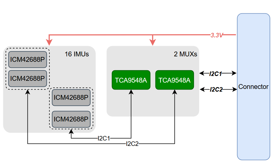
The PCB is designed with a 6-layer stackup:
This multi-layer design ensures proper signal integrity, power distribution, and electromagnetic compatibility for the IMU array sensor system.
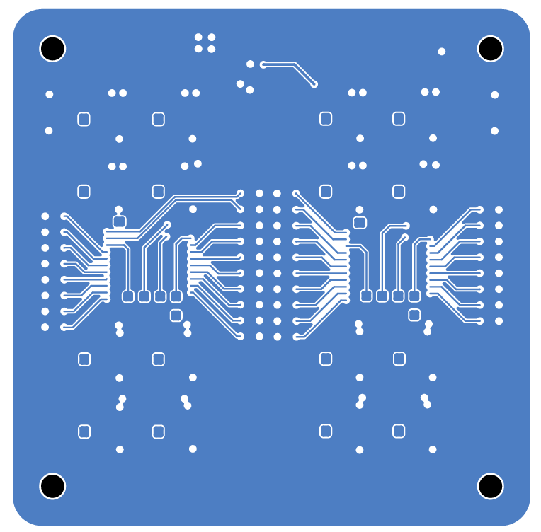
Complete PCB Layout:
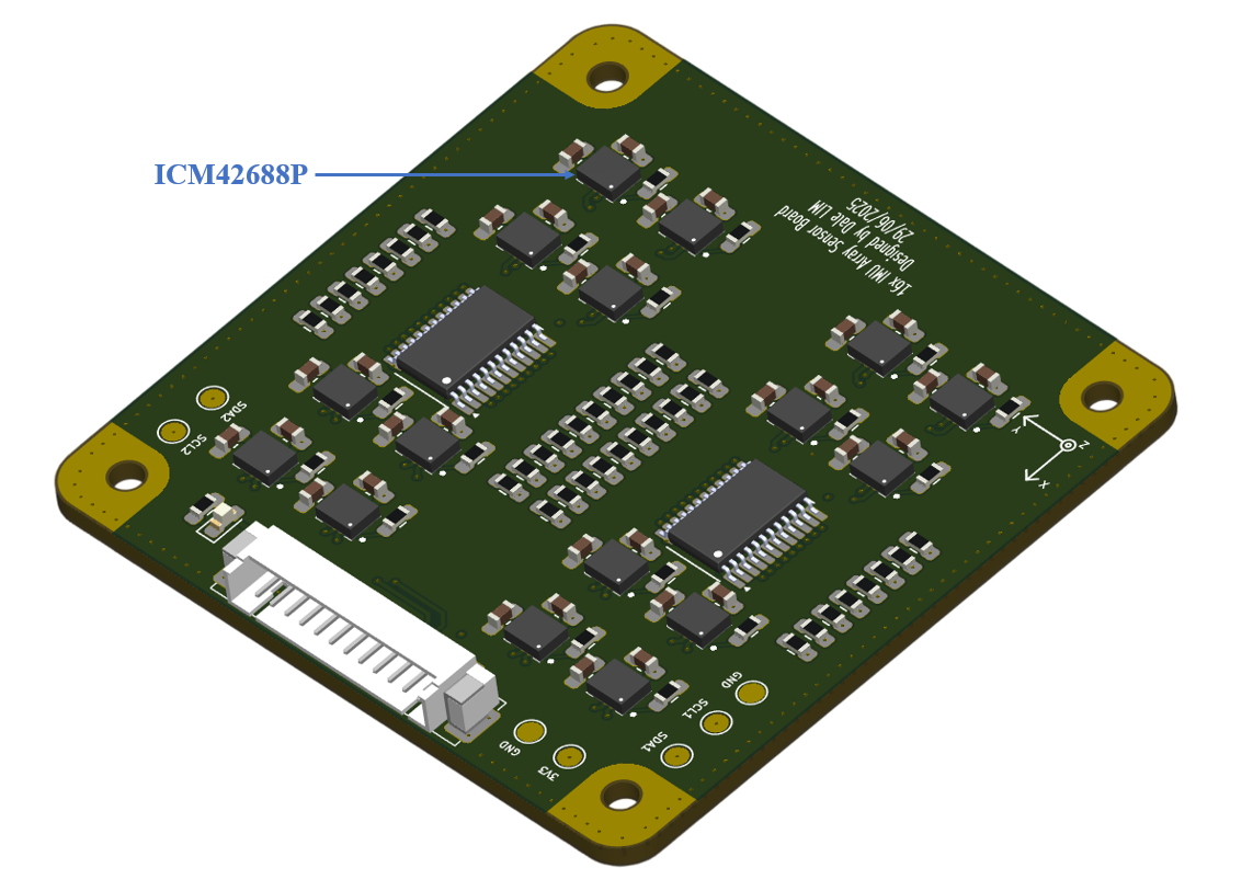
Layer 1:
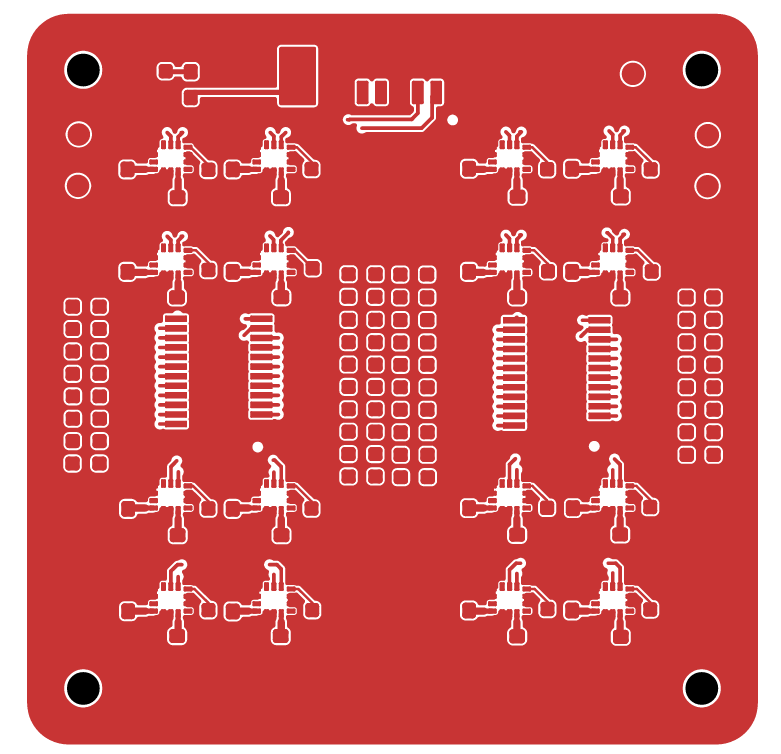
Layer 3:
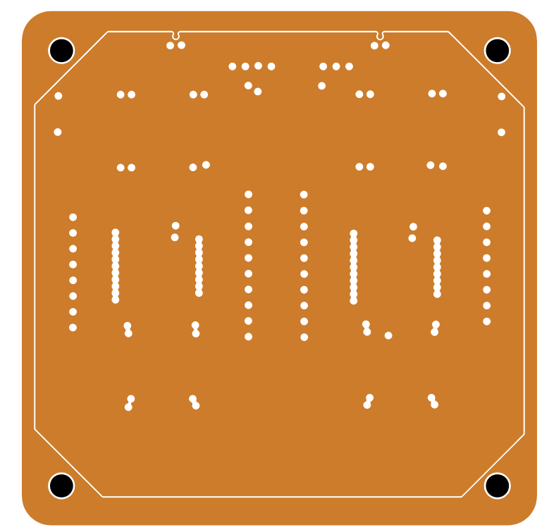
Layer 4:
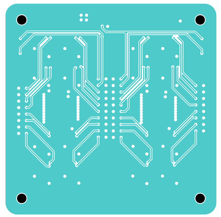
Layer 6:
To verify the hardware connectivity of the IMU array sensor board, upload the provided firmware to your STM32 microcontroller:
fimware_check/STM32F401.binfimware_check/STM32F401.hexUpload either the .bin or .hex file to your STM32F401 microcontroller to test and validate the hardware connectivity of all IMU sensors in the array. This firmware will help you verify that:
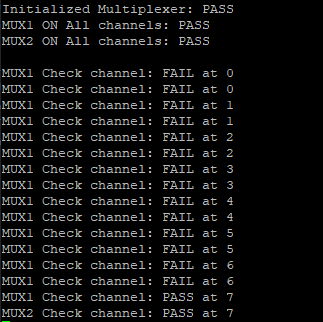
The expected result shows channel 7 of both multiplexers working correctly with sensors at address 0x68, demonstrating proper hardware connectivity and communication with the IMU array.
| Qty | Value | Footprint | References |
|---|---|---|---|
| 36 | 4.7k | Resistor_SMD:R_0603_1608Metric_Pad0.98x0.95mm_HandSolder | R1, R2, R3, R14, R15, R17, R18, R20, R21, R23, R24, R26, R27, R28, R29, R30 +20 |
| 24 | 10k | Resistor_SMD:R_0603_1608Metric_Pad0.98x0.95mm_HandSolder | R10, R11, R12, R16, R19, R22, R25, R34, R35, R36, R37, R46, R47, R48, R49, R58 +8 |
| 18 | 100nF | Capacitor_SMD:C_0603_1608Metric_Pad1.08x0.95mm_HandSolder | C1, C2, C3, C12, C15, C16, C17, C18, C27, C28, C29, C30, C39, C40, C41, C42 +2 |
| 16 | 10nF | Capacitor_SMD:C_0603_1608Metric_Pad1.08x0.95mm_HandSolder | C4, C7, C10, C13, C19, C20, C21, C22, C31, C32, C33, C34, C43, C44, C45, C46 |
| 16 | 2.2uF | Capacitor_SMD:C_0603_1608Metric_Pad1.08x0.95mm_HandSolder | C5, C8, C11, C14, C23, C24, C25, C26, C35, C36, C37, C38, C47, C48, C49, C50 |
| 16 | ICM-42688-P | Sensor_board:PQFN50P300X250X97 | U3, U4, U5, U6, U7, U8, U9, U10, U11, U12, U13, U14, U15, U16, U17, U18 |
| 7 | TestPoint | TestPoint:TestPoint_Pad_D1.5mm | TP3, TP4, TP5, TP6, TP7, TP8, TP9 |
| 4 | MountingHole | MountingHole:MountingHole_2.2mm_M2 | H1, H2, H3, H4 |
| 2 | TCA9548APWR | Sensor_board:TSSOP24_1.2mm | U1, U2 |
| 1 | 1k | Resistor_SMD:R_0603_1608Metric_Pad0.98x0.95mm_HandSolder | R13 |
| 1 | Conn_01x14 | Sensor_board:1.25-12P WT | J1 |
| 1 | RED | LED_SMD:LED_0603_1608Metric_Pad1.05x0.95mm_HandSolder | D2 |
It measures 50 × 50 mm and has 6 copper layers, 1.57 mm thick.
142 parts, built around the ICM-42688-P. The full list of its parts is on this page, with links to each part's symbol and footprint where PCBKit's library has them.
From the dale-lim29/Hardware_IMU_Array_Sensor repository on GitHub, at the commit this page was made from: the board is Sensor_board.kicad_pcb and its schematic Sensor_board.kicad_sch. PCBKit opens the board in the browser, with nothing to install.
Its repository states no licence, so its author keeps all rights: ask dale-lim29 before reusing the design.
will127534/OneInchEye
A One Inch CMOS sensor (IMX283) camera board designed for Raspberry Pi


rishikesh2715/STM32F7_FC
STM32F722RET6 Based Flight Controller with ICM-42688-P IMU, BMP388 Barometer, and much more!

fdiwth/tvc-drone
This repository contains the documentation, hardware designs, and source code for a Thrust Vector Control (TVC) drone.

will127534/GlobalEye
A simple camera board using GMAX3412 1" 4K@30fps global shutter sensor

Open-Muscle/OpenMuscle-FlexGrid
60-sensor wearable with flexible PCB and pressure matrix

