4 layers17.8 × 38.1 mm

 daglem/reDIP-6420
Commodore 64 FPGA emulation platform
ReDIP-64 is an open-source printed circuit board by daglem, from the daglem/reDIP-64 repository on GitHub. It is a 6-layer board of 25.4 × 50.8 mm with 150 parts on 312 nets, routed with 3,373 tracks and 833 vias.
It is built around the LFE5UM5G-25F-8MG285C, FUSB340TMX and PTN5110NHQZ, with the SGTL5000XNLA3, W25Q128JVPIM and W957A8MFYA5I among its other parts. Its parts include 70 capacitors, 27 resistors, 23 ICs, 5 connectors and 4 diodes. It belongs with the FPGA and CPLD boards of this library.


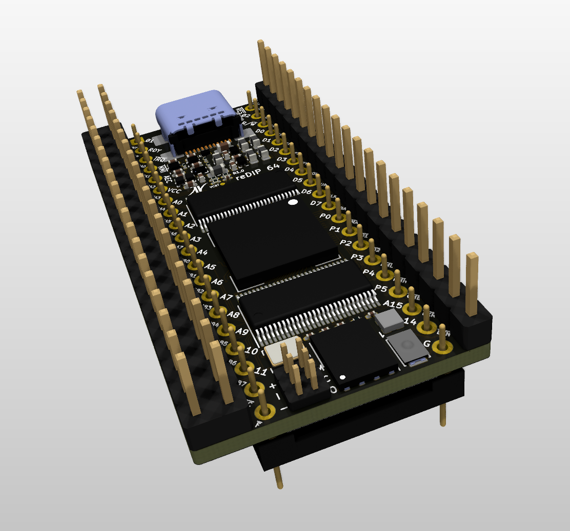
The reDIP 64 is an open source hardware development board which combines the following in a tiny 25.40 x 50.80 mm footprint:
The reDIP 64 aims at functioning as
Designs for the ECP5 FPGA can be processed by yosys and nextpnr.
Also check out the reDIP SID, if you are interested in a platform for MOS 6581 / 8580 SID emulation in particular.
All FPGA I/O is 5V tolerant, and can drive 5V TTL.
Note that the audio line inputs are not AC coupled - AC coupling must be externally added for audio applications. Without external AC coupling, the line inputs can conceivably be used as generic ADCs.
A separate 6 pin header is provided for JTAG.
The board is pin compatible with the MOS 6510 / 8500 MPU chip, and has additional pin headers to cover all the custom chips and I/O in the Commodore 64:
For anyone interested in experimenting with a Commodore 64 setup, while avoiding blown fuses and a broken reDIP 64 board:
The idea is that one can start by mounting the reDIP 64 in a Commodore 64, replacing the 6510 / 8500 MPU. This will make it possible to communicate with the Commodore 64 via USB, to output audio and video via the USB-C connector (DP Alt Mode), and to emulate a second SID chip.
Then, if one wishes to replace the VIC-II, the SID, or a CIA chip, the custom chip is removed, and wires are run from the reDIP 64 to the corresponding socket pins for the custom chip.
Note that the audio line outputs cannot drive the C64 audio output stage directly, however an audio output may be connected directly to pin 3 of the C64 audio/video connector (preferably removing or cutting a pin on C13 in the C64).
Also note that unless suggested GPIO is repurposed for other functions, the VIC-II can only be replaced by additionally emulating all RAM chips, and the PLA can only be replaced by emulating all custom chips, including ROM and RAM.
The MOS 8502 MPU used in the Commodore C128 has a similar pinout to the MOS 6510. Since the same pins are used for power, the reDIP 64 can conceivably also be used in a C128.
Power, HID input, and audio / video can all be handled via the USB-C port, hence the reDIP 64 is in fact capable of operating as a retro computer all on its own. Just connect the reDIP 64 to a DisplayPort monitor, either directly or via an USB hub, and add a keyboard and any other HID input devices. Now, all that is needed is an FPGA implementation of a retro computer :wink:
To create a fully functional retro computer, i.e. with I/O which can interface with original perhiperals, physical connectors and glue logic must be added to the mix. This can make for some fun projects!
Using the suggested GPIO, a fully functional custom C64 can be built using a minimum of additional components.
The board can be of course also be used to experiment with e.g.
Please note that this is only my third board design - rookie mistakes are probably made, and feedback is welcome.
| Board Front | Board Back |
|---|---|
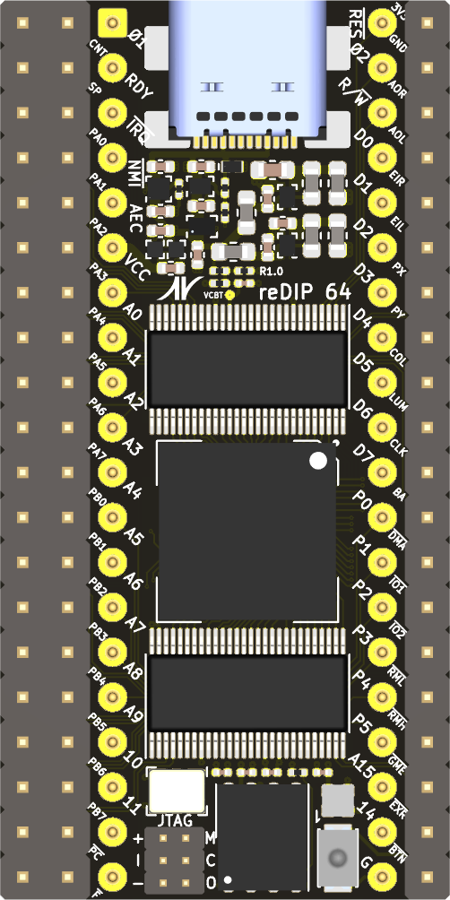 | 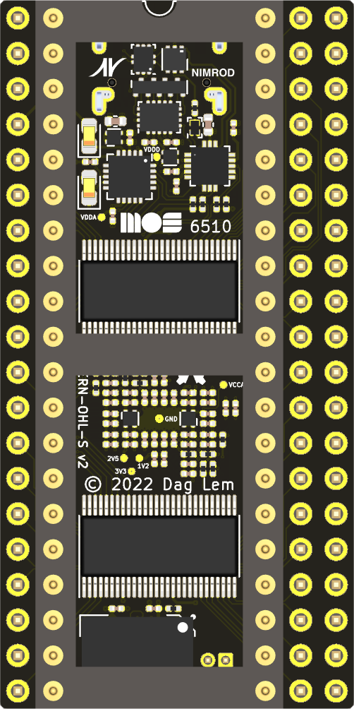 |
| Qty | Value | Footprint | References |
|---|---|---|---|
| 26 | 0.1uF | Capacitor_SMD:C_0201_0603Metric | C32, C33, C34, C35, C36, C38, C40, C42, C44, C46, C48, C50, C52, C54, C56, C58 +10 |
| 23 | 1uF | Capacitor_SMD:C_0201_0603Metric | C2, C3, C4, C23, C24, C25, C26, C28, C29, C30, C31, C37, C39, C41, C43, C45 +7 |
| 9 | 1uF | Capacitor_SMD:C_0402_1005Metric | C1, C13, C14, C15, C16, C17, C19, C20, C27 |
| 8 | TestPoint | reDIP:TestPoint_Pad_D0.5mm | TP1, TP2, TP3, TP4, TP5, TP6, TP7, TP8 |
| 6 | 100nF | Capacitor_SMD:C_0201_0603Metric | C5, C7, C8, C9, C10, C11 |
| 6 | 4.7k | Resistor_SMD:R_0201_0603Metric | R21, R22, R23, R25, R26, R27 |
| 4 | 10k | Resistor_SMD:R_0201_0603Metric | R3, R4, R11, R14 |
| 4 | BLM18KG601SN1 | Inductor_SMD:L_0603_1608Metric | FB1, FB2, FB3, FB4 |
| 4 | SN74CBT16211ADGVR | TI:Texas_TVSOP-56_4.4x11.3mm_P0.4mm | U17, U18, U19, U20 |
| 3 | 100 | Resistor_SMD:R_0201_0603Metric | R8, R12, R13 |
| 3 | 22 | Resistor_SMD:R_0201_0603Metric | R6, R7, R24 |
| 2 | 100k | Resistor_SMD:R_0201_0603Metric | R9, R10 |
| 2 | 10uF | Capacitor_Tantalum_SMD:CP_EIA-1608-08_AVX-J | C69, C70 |
| 2 | 1k | Resistor_SMD:R_0201_0603Metric | R16, R18 |
| 2 | 2.2k | Resistor_SMD:R_0201_0603Metric | R1, R2 |
| 2 | 2.2uF | Capacitor_SMD:C_0402_1005Metric | C12, C21 |
| 2 | G*** | reDIP:Nimrod-N-small | svg2mod, svg2mod |
| 2 | NCP163AMX120TBG | ONSemi:CASE_711AJ_1.0x1.0mm_P0.65mm | U13, U16 |
| 2 | TPS22916CN | TI:Texas_DSBGA-4_0.78x0.78mm_Layout2x2_P0.4mm | U8, U11 |
| 1 | 1.07k | Resistor_SMD:R_0201_0603Metric | R17 |
| 1 | 1.5k | Resistor_SMD:R_0201_0603Metric | R5 |
| 1 | 10uF | Capacitor_SMD:C_0603_1608Metric | C18 |
| 1 | 10uF | Capacitor_SMD:C_0402_1005Metric | C22 |
| 1 | 1uH | Inductor_SMD:L_0603_1608Metric | L1 |
| 1 | 3.83k | Resistor_SMD:R_0201_0603Metric | R15 |
| 1 | 470nH | Inductor_SMD:L_0603_1608Metric | L2 |
| 1 | 6.2k | Resistor_SMD:R_0201_0603Metric | R20 |
| 1 | Conn_01x20 | reDIP:PinHeader_1x20_P2.54mm_Vertical | J3 |
| 1 | Conn_02x05_Odd_Even | reDIP:PinHeader_2x03_P1.27mm_Vertical | J5 |
| 1 | Conn_02x20_Counter_Clockwise | reDIP:DIP-40_W15.24mm_Header | J2 |
| 1 | Conn_02x20_Odd_Even | reDIP:PinHeader_2x20_P2.54mm_Vertical | J4 |
| 1 | D3V3F8U9LP3810 | Diodes:U-DFN3810-9 | D3 |
| 1 | DSC1103CE2-135.0000 | Microchip:Oscillator_SMD_3225-6Pin_3.2x2.5mm | U4 |
| 1 | ESD7241 | ONSemi:CASE_714AB_1.0x0.6mm | D1 |
| 1 | FAN53610 | ONSemi:CASE_567RQ_1.16x0.86mm_P0.4mm | U9 |
| 1 | FAN53611 | ONSemi:CASE_567RQ_1.16x0.86mm_P0.4mm | U12 |
| 1 | FPF1048 | ONSemi:CASE_567RM_1.46x0.96mm_P0.5mm | U7 |
| 1 | FPF2286 | ONSemi:CASE_567UV_1.30x0.90mm_P0.4mm | U6 |
| 1 | FPF2495C | ONSemi:CASE_567RV_1.21x1.21mm_P0.4mm | U10 |
| 1 | FSUSB42UMX | ONSemi:CASE_523BC_1.4x1.8_P0.4mm | U5 |
| 1 | FUSB340 | ONSemi:CASE_722AB_2.0x2.8mm_P0.4mm | U3 |
| 1 | G*** | reDIP:MOS-logo-small | svg2mod |
| 1 | G*** | reDIP:OSHW-logo | OSHW logo |
| 1 | G*** | reDIP:Nimrod-text-small | svg2mod |
| 1 | KXT311LHS | CK:SW_SPST_CK_KXT3 | SW1 |
| 1 | LFE5UM5G-25F-8MG285C | Lattice:BGA-285_10x10mm_P0.5mm | U2 |
| 1 | NC | Resistor_SMD:R_0201_0603Metric | R19 |
| 1 | NCP115AMX250TCG | ONSemi:CASE_711AJ_1.0x1.0mm_P0.65mm | U14 |
| 1 | NCP163AMX330TBG | ONSemi:CASE_711AJ_1.0x1.0mm_P0.65mm | U15 |
| 1 | PDTA143ZMB | Nexperia:SOT-883 | Q1 |
| 1 | PTN5110NHQ | NXP:SOT-1883-1 | U1 |
| 1 | SGTL5000XNLA3 | Package_DFN_QFN:QFN-20-1EP_3x3mm_P0.4mm_EP1.65x1.65mm | U23 |
| 1 | SMD-LX0707RGB-TR | Lumex:SMD-LX0707RGB-TR | D4 |
| 1 | USB4080 | GCT:USB_C_Receptacle_GCT_USB4080 | J1 |
| 1 | VESD05A6-HAF | Vishay:LLP75-7L | D2 |
| 1 | W25Q128JVPIM | Package_SON:WSON-8-1EP_6x5mm_P1.27mm_EP3.4x4.3mm | U22 |
| 1 | W957A8MFYA5I | Winbond:TFBGA-24_6.0x8.0mm_P1mm | U21 |
It measures 25.4 × 50.8 mm and has 6 copper layers, 1.57 mm thick.
150 parts, built around the LFE5UM5G-25F-8MG285C, FUSB340TMX, PTN5110NHQZ and SGTL5000XNLA3. The full list of its parts is on this page, with links to each part's symbol and footprint where PCBKit's library has them.
From the daglem/reDIP-64 repository on GitHub, at the commit this page was made from: the board is hardware/reDIP-64.kicad_pcb and its schematic hardware/reDIP-64-Audio.kicad_sch. PCBKit opens the board in the browser, with nothing to install.
Its repository states no licence, so its author keeps all rights: ask daglem before reusing the design.


osqzss/PocketSDR
The Pocket SDR FE device includes 2, 4, or 8 RF frontend channels, supporting the GNSS L1 band (1525 - 1610 MHz) or L2/L5/L6 bands (1160 - 1290 MHz). For these signal bands, refer to GNSS Signal Bands.

n4subishin/nb1-keyboard
Nb.1 - A 12-position programmable macropad with swappable Cherry MX switches and rotary encoders (STM32F405 / QMK / Remap) Nb.1 - Cherry MX互換スイッチとロータリーエンコーダーを搭載した、12キー左手デバイス(STM32F405 / QMK / Remap対応)

RobotPatient/Manikin_Color_Hub
Led driver board files, flexible led strip files and (partially finished) software to drive them. And all our documentation. Part of the skin colour research group.

