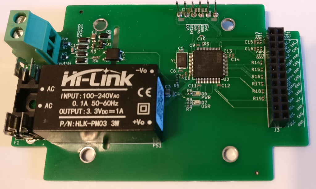
2 layers130 × 110 mm
3D Printer Mainboard STM32
m47812/Custom-3D-Printer-Controller
A fully custom 3D Printer controller board based on an stm32f7 controller with TMC2209 stepper drivers
191 parts10GPL-3.0
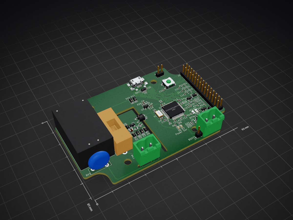
 cs2dsb/zcssr10
A PCB and software for a SSR controller that monitors mains AC zero crossings to determine when to turn the SSR on.
Zero crossing detector is an open-source printed circuit board by cs2dsb, from the cs2dsb/zcssr repository on GitHub, published under the Apache-2.0 licence. It is a 2-layer board of 93 × 61 mm with 98 parts on 91 nets, routed with 779 tracks and 158 vias.
It is built around the HLK-PM01, MAX31855KASA+T and AP2112K-3.3, with the EL357N(C)(TA)-G, USBLC6-2SC6 and B5819W among its other parts. Its parts include 36 resistors, 23 capacitors, 11 diodes, 6 connectors and 5 ICs. It belongs with the STM32 boards of this library.


A PCB and software for a SSR controller that monitors mains AC zero crossings to determine when to turn the SSR on.
I wanted to build a spot welder from an old MOT (microwave oven transformer) but wasn't satisfied with simply enabling the SSR at random because this makes the pulse +/- 1 half mains cycle (10ms on 50Hz, 8.3ms on 60Hz). It probably doesn't make much difference in the grand scheme of things but I wanted to know exactly how long the pulses were.
This controller solves that issue by monitoring the mains zero crossing and triggering the SSR just before a zero crossing - the SSR has it's own zero crossing circuit to actually turn on it's output so as long as the controller doesn't fire more than 1 cycle early it will work as expected.
I also wanted to completely finish an embedded project written in rust and this project seemed about the right size undertaking.
Not a complete list. Will add to it as features get implemented
./bootstrap script which will:
firmware/bootstrap which will:
gcc, gdb, openocd and libudev-devsudo firmware/install_apt_deps will install these deps if you are using a distribution that uses aptfirmware/deploy_standalone will start openocd, flash the program and restart the devicefirmware/run_openocd in one terminalfirmware/release or firmware/debug to build and launch gdbfirmware/openocd.gdb and the scripts above to tweak the behaviour--feature itm will log over SWDfirmware/monitor_itm will launch serialitm to print this output with the ITM control characters stripped out. You may need to tweak the script if your uart dongle isn't /dev/ttyUSB0firmware/tmux_workspace is a script that will open a tmux session with firmware/run_openocd, firmware/monitor_itm and firmware/watch in differnt panes to make development easy. Just type ./release in one of the spare panes to deploy the software with gdbThe code uses ITM logging to indicate start up progress and log info like temperatures and user config. If the ITM feature is enabled, the microcontroller won't run without openocd connected because there is some debug config openocd does to the chip that makes ITM work. I've added the obvious checks to the itm_logger crate but there's still something missing that I haven't got to the bottom of yet. There's an issue to track it. The bottom line is if you want to be able to plug the hardware into the mains without OpenOCD connected you need to disable the itm feature (firmware/deploy_standalone already does this.)
Check the docs folder for information on setting up the dev environment and various info on making the hardware.
This template is licensed under either of
Apache License, Version 2.0 (LICENSE-APACHE or http://www.apache.org/licenses/LICENSE-2.0)
MIT license (LICENSE-MIT or http://opensource.org/licenses/MIT)
at your option.
| Qty | Value | Footprint | References |
|---|---|---|---|
| 18 | 10k | Resistor_SMD:R_0402_1005Metric | R10, R11, R12, R13, R14, R15, R18, R20, R21, R27, R28, R29, R30, R31, R32, R35 +2 |
| 9 | 100nF | Capacitor_SMD:C_0402_1005Metric | C4, C9, C10, C11, C13, C14, C19, C20, C21 |
| 7 | 1N4148 | Diode_SMD:D_SOD-123 | D1, D2, D3, D4, D5, D9, D12 |
| 6 | 10nf | Capacitor_SMD:C_0402_1005Metric | C8, C15, C16, C17, C22, C23 |
| 3 | 1k | Resistor_SMD:R_0402_1005Metric | R6, R33, R34 |
| 3 | 2N3904 | Package_TO_SOT_SMD:SOT-23 | Q1, Q2, Q3 |
| 2 | 100k | Resistor_SMD:R_0402_1005Metric | R25, R26 |
| 2 | 10uF | Capacitor_SMD:C_0402_1005Metric | C3, C18 |
| 2 | 150 | Resistor_SMD:R_0402_1005Metric | R16, R17 |
| 2 | 2.2k | Resistor_SMD:R_0402_1005Metric | R19, R40 |
| 2 | 22 | Resistor_SMD:R_0402_1005Metric | R22, R23 |
| 2 | 220k | Resistor_SMD:R_0805_2012Metric | R1, R2 |
| 2 | 22pF | Capacitor_SMD:C_0402_1005Metric | C5, C6 |
| 2 | 600ohm | Inductor_SMD:L_0805_2012Metric | FB1, FB2 |
| 2 | B5819W | Diode_SMD:D_SOD-123 | D10, D11 |
| 2 | SolderJumper_2_Open | Custom:SolderJumper-2_P1.3mm_Open_TrianglePad1.0x1.5mm | JP1, JP2 |
| 1 | 10uF | Capacitor_SMD:C_0805_2012Metric | C2 |
| 1 | 1k | Resistor_SMD:R_0603_1608Metric | R4 |
| 1 | 1nF | Capacitor_SMD:C_0603_1608Metric | C1 |
| 1 | 1uf | Capacitor_SMD:C_0402_1005Metric | C7 |
| 1 | 220 | Resistor_SMD:R_0402_1005Metric | R8 |
| 1 | 22k | Resistor_SMD:R_0603_1608Metric | R3 |
| 1 | 2k | Resistor_SMD:R_0402_1005Metric | R24 |
| 1 | 4.7k | Resistor_SMD:R_0402_1005Metric | R5 |
| 1 | 4.7uf | Capacitor_SMD:C_0402_1005Metric | C12 |
| 1 | 500mA 250V Slow Blow | Fuse:Fuseholder_Cylinder-5x20mm_Stelvio-Kontek_PTF78_Horizontal_Open | F1 |
| 1 | 8MHz | Crystal:Crystal_SMD_5032-2Pin_5.0x3.2mm | Y1 |
| 1 | AP2112K-3.3 | Package_TO_SOT_SMD:SOT-23-5 | U3 |
| 1 | BOOT0 | Connector_PinHeader_2.54mm:PinHeader_1x02_P2.54mm_Vertical | J2 |
| 1 | BOOT1 | Connector_PinHeader_2.54mm:PinHeader_1x02_P2.54mm_Vertical | J7 |
| 1 | Conn_01x02 | Custom:Terminal_Block_Dinkle_EK508V_1x02_P5.08mm_Vertical | J1 |
| 1 | Conn_02x15_Odd_Even | Connector_PinHeader_2.54mm:PinHeader_2x15_P2.54mm_Vertical | J3 |
| 1 | EL357N(C)(TA)-G | Package_SO:SOP-4_3.8x4.1mm_P2.54mm | U1 |
| 1 | HLK-PM01 | Converter_ACDC:Converter_ACDC_HiLink_HLK-PMxx | PS1 |
| 1 | K-Type | Custom:PhoenixContact_MKDS_2-3.5 | J6 |
| 1 | MAX31855KASA | Package_SO:SOIC-8_3.9x4.9mm_P1.27mm | U4 |
| 1 | PWR_Green | LED_SMD:LED_0603_1608Metric | D6 |
| 1 | Reset | Button_Switch_SMD:SW_SPST_B3SL-1002P | SW1 |
| 1 | STM32F103RCTx | Package_QFP:LQFP-64_10x10mm_P0.5mm | U2 |
| 1 | USBLC6-2SC6 | Package_TO_SOT_SMD:SOT-23-6 | U5 |
| 1 | USB_B_Micro | Custom:ZX62M-B-5P(30) | J4 |
| 1 | USR_Red | LED_SMD:LED_0603_1608Metric | D7 |
| 1 | Varistor | Varistor:RV_Disc_D12mm_W3.9mm_P7.5mm | RV1 |
The 93 most common of 98 parts.
It measures 93 × 61 mm and has 2 copper layers, 1.6 mm thick.
98 parts, built around the HLK-PM01, MAX31855KASA+T, AP2112K-3.3 and EL357N(C)(TA)-G. The full list of its parts is on this page, with links to each part's symbol and footprint where PCBKit's library has them.
From the cs2dsb/zcssr repository on GitHub, at the commit this page was made from: the board is hardware/zero_crossing_detector_surface_mount/zero_crossing_detector.kicad_pcb. PCBKit opens the board in the browser, with nothing to install.
Its repository publishes it under the Apache-2.0 licence: you may reuse it on that licence's terms (keep the author's notice, and for a copyleft licence share your changes alike).
m47812/Custom-3D-Printer-Controller
A fully custom 3D Printer controller board based on an stm32f7 controller with TMC2209 stepper drivers

energietransitie/twomes-opentherm-monitor-hardware
Open hardware design files for the Twomes OpenTherm Monitor device


stasiselectronics/HotPlateController
A simple ESP32 connected controller for a SMD reflow hot plate


cs2dsb/stm32-usb.rs
A dev board designed to facilitate the development of USB firmware for STM32

Woz4tetra/auto-battlebot
This project brings aim-assist and autonomous control to combat robots.

anhldptit2610/dalws
This project is my attempt to learn about microcontroller and PCB design. Now I realize that making a full, complete electronic project is super hard.