2 layers60 × 45 mm

 anhldptit2610/dalws2
This project is my attempt to learn about microcontroller and PCB design. Now I realize that making a full, complete electronic project is super hard.
Dalws is an open-source printed circuit board by anhldptit2610, from the anhldptit2610/dalws repository on GitHub, published under the MIT licence. It is a 4-layer board of 64 × 43 mm with 83 parts on 80 nets, routed with 663 tracks and 106 vias.
It is built around the AP2112K-3.3, DS3231MZ+TRL and LIS3DH, with the MCP73831T-2ACI/OT-HXY, USBLC6-2SC6 and 1N5819WS among its other parts. Its parts include 23 resistors, 21 capacitors, 8 ICs, 6 diodes and 4 transistors. It belongs with the STM32 boards of this library.


A portable handheld device.
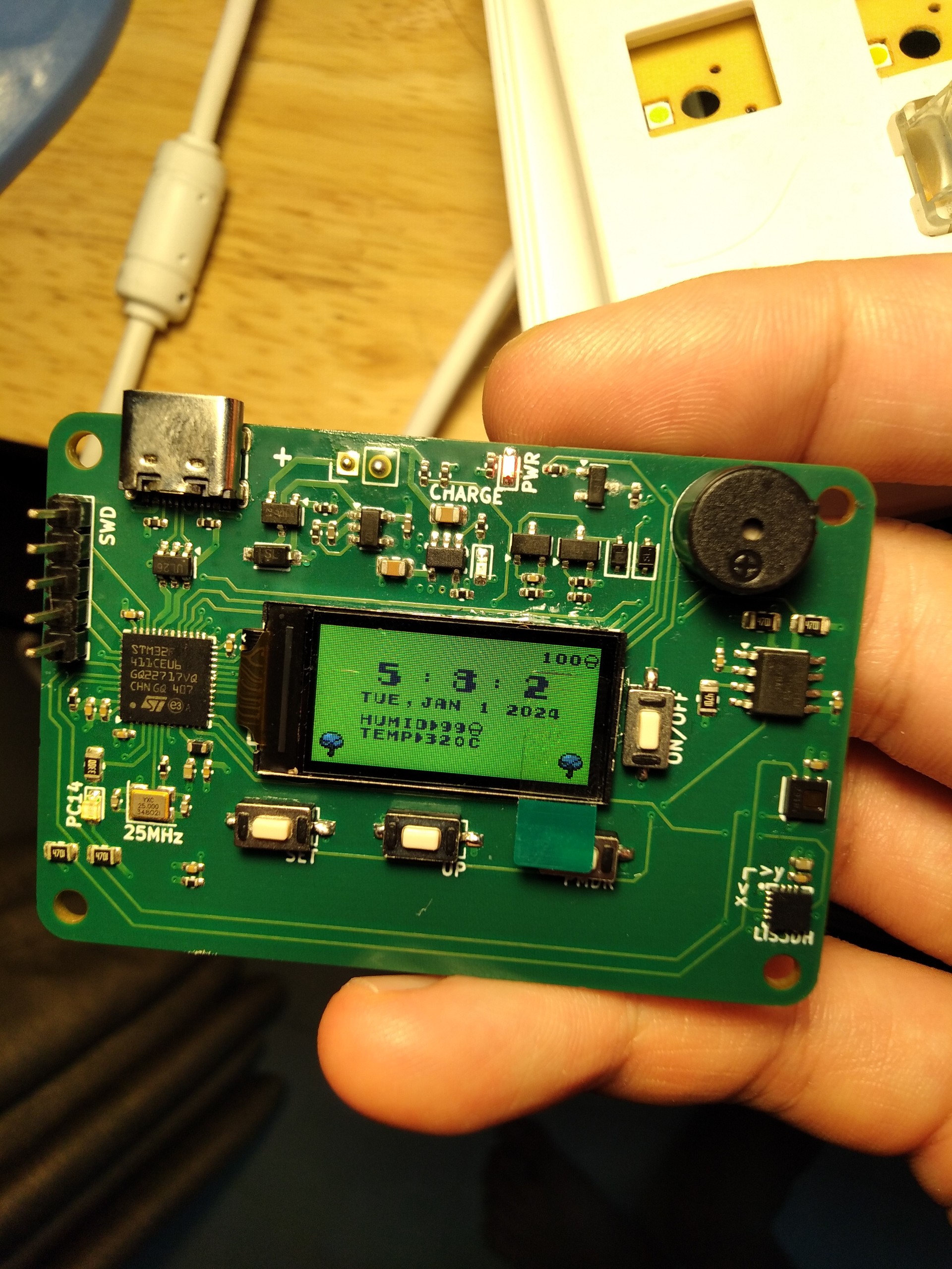
This project is my attempt to learn about microcontroller and PCB design. Now I realize that making a full, complete electronic project is super hard. I made all the steps in this project, from designing the PCB to program the firmware. To be honest, the PCB design process is harder. Choose components, read the datasheets and lots of schematics, make a design, review and fix errors, quite a lot of work. But it's worth all the pennies and efforts I spent for this project.
See this
See BOM. The BOM doesn't contain ST7735's LCD screen and buttons.
You can install above dependencies by using these commands(Ubuntu/any Debian based Linux distro):
$ sudo apt update
$ sudo apt install arm-none-eabi-gcc build-essential$ git clone --recurse-submodules https://github.com/anhldptit2610/dalws.git
$ cd dalws/firmware/dalws
$ makeUse the ST's STM32CubeProgrammer to flash the binary.
| Qty | Value | Footprint | References |
|---|---|---|---|
| 9 | 100n | Capacitor_SMD:C_0402_1005Metric_Pad0.74x0.62mm_HandSolder | C1, C3, C5, C6, C7, C8, C12, C18, C22 |
| 7 | LOGO | LOGO | G***, G***, G***, G***, G***, G***, G*** |
| 5 | 100k | Resistor_SMD:R_0402_1005Metric_Pad0.72x0.64mm_HandSolder | R1, R2, R4, R7, R13 |
| 5 | 4.7k | Resistor_SMD:R_0805_2012Metric | R10, R11, R18, R19, R20 |
| 4 | 0.1u | Capacitor_SMD:C_0402_1005Metric_Pad0.74x0.62mm_HandSolder | C2, C13, C16, C17 |
| 4 | MountingHole | MountingHole:MountingHole_2.7mm_M2.5_DIN965 | H1, H2, H3, H4 |
| 4 | SW_Push | alcato:GT-TC060A-H025-L1 | SW1, SW2, SW3, SW5 |
| 2 | 10k | Resistor_SMD:R_0402_1005Metric_Pad0.72x0.64mm_HandSolder | R9, R15 |
| 2 | 10u | Capacitor_SMD:C_0402_1005Metric_Pad0.74x0.62mm_HandSolder | C9, C11 |
| 2 | 15p | Capacitor_SMD:C_0402_1005Metric_Pad0.74x0.62mm_HandSolder | C4, C10 |
| 2 | 1N5819WS | Diode_SMD:D_SOD-323 | D2, D6 |
| 2 | 1k | Resistor_SMD:R_0402_1005Metric_Pad0.72x0.64mm_HandSolder | R12, R17 |
| 2 | 1u | Capacitor_SMD:C_0402_1005Metric_Pad0.74x0.62mm_HandSolder | C14, C15 |
| 2 | 4.7u | Capacitor_SMD:C_0805_2012Metric | C19, C20 |
| 2 | 5k1 | Resistor_SMD:R_0402_1005Metric_Pad0.72x0.64mm_HandSolder | R5, R6 |
| 2 | AO3401A | Package_TO_SOT_SMD:SOT-23 | Q1, Q2 |
| 2 | KT-0603R | LED_SMD:LED_0603_1608Metric_Pad1.05x0.95mm_HandSolder | D1, D4 |
| 1 | 0 | Resistor_SMD:R_0402_1005Metric_Pad0.72x0.64mm_HandSolder | R8 |
| 1 | 1M | Resistor_SMD:R_0402_1005Metric_Pad0.72x0.64mm_HandSolder | R3 |
| 1 | 22 | Resistor_SMD:R_0402_1005Metric_Pad0.72x0.64mm_HandSolder | R14 |
| 1 | 25MHz | Crystal:Crystal_SMD_3225-4Pin_3.2x2.5mm | Y1 |
| 1 | 2k | Resistor_SMD:R_0402_1005Metric_Pad0.72x0.64mm_HandSolder | R21 |
| 1 | 330 | Resistor_SMD:R_0805_2012Metric | R24 |
| 1 | 330 | Resistor_SMD:R_0402_1005Metric_Pad0.72x0.64mm_HandSolder | R16 |
| 1 | 470 | Resistor_SMD:R_0402_1005Metric_Pad0.72x0.64mm_HandSolder | R22 |
| 1 | AO3400A | Package_TO_SOT_SMD:SOT-23 | Q3 |
| 1 | AP2112K-3.3 | Package_TO_SOT_SMD:SOT-23-5 | U1 |
| 1 | B5819W | B5819W:B5819W | D3 |
| 1 | BATT | Connector_PinHeader_2.54mm:PinHeader_1x02_P2.54mm_Vertical | BT2 |
| 1 | BLM18AG601SN1D | digikey-footprints:0603 | FB2 |
| 1 | Buzzer | speaker:TMB09A05 | BZ1 |
| 1 | DS3231MZ+TRL | Package_SO:SOIC-8_3.9x4.9mm_P1.27mm | U2 |
| 1 | HDC1080 | Package_SON:Texas_PWSON-N6 | U6 |
| 1 | KT-0805G | LED_SMD:LED_0603_1608Metric_Pad1.05x0.95mm_HandSolder | D5 |
| 1 | LIS3DH | alcato:LIS3DHTR | U3 |
| 1 | MCP73831T-2ACI/OT | digikey-footprints:SOT-753 | U5 |
| 1 | MMBT2222A 1P | Package_TO_SOT_SMD:SOT-23 | Q5 |
| 1 | STM32F411CEUx | Package_DFN_QFN:QFN-48-1EP_7x7mm_P0.5mm_EP5.6x5.6mm | U8 |
| 1 | SWD | Connector_PinHeader_2.54mm:PinHeader_1x05_P2.54mm_Vertical | J3 |
| 1 | USBC | Connector_USB:USB_C_Receptacle_G-Switch_GT-USB-7010ASV | J1 |
| 1 | USBLC6-2SC6 | Package_TO_SOT_SMD:SOT-23-6 | U4 |
| 1 | ~ | alcato:OLED-SMD_ST7735S | U7 |
It measures 64 × 43 mm and has 4 copper layers, 1.61 mm thick.
83 parts, built around the AP2112K-3.3, DS3231MZ+TRL, LIS3DH and MCP73831T-2ACI/OT-HXY. The full list of its parts is on this page, with links to each part's symbol and footprint where PCBKit's library has them.
From the anhldptit2610/dalws repository on GitHub, at the commit this page was made from: the board is hardware/dalws/dalws.kicad_pcb and its schematic hardware/dalws/dalws.kicad_sch. PCBKit opens the board in the browser, with nothing to install.
Its repository publishes it under the MIT licence: you may reuse it on that licence's terms (keep the author's notice, and for a copyleft licence share your changes alike).

yesnoj/FilMachine_Reworked
FilMachine is an automated film processing machine designed for photographic film development. It handles the entire process: chemical baths, water rinses, temperature regulation, and motor-driven film agitation — all…


ilomon10/embedded-totalizer-hour-meter
ESP32 engine hour meter & totalizer: firmware, SensorFrame protocol, Node host tools, KiCad PCB and a Deno device simulator


Kilan777/HomeDeck
Jarvis HomeDeck: a Raspberry Pi CM4 carrier board and voice-assistant software for a 7-inch smart display (KiCad hardware, generated from Python, plus the Python/JS assistant)


DashiellRussell/UNSW_Rocketry_Senior_Flight_Computer
KiCad project for the senior flight computer used by UNSW Rocketry.