4 layers22 × 15 mm
Amp cpw hmc311
loxodes/vna
Under development open hardware microwave vector network analyzer
67 parts205

 CRTified/CANdiBar1
A small CAN hub and power distribution board for multiple devices
CANdiBar is an open-source printed circuit board by CRTified, from the CRTified/CANdiBar repository on GitHub, published under the MIT licence. It is a 4-layer board of 88 × 44 mm with 67 parts on 75 nets, routed with 570 tracks and 78 vias.
Its parts include 20 ICs, 16 capacitors, 16 resistors and 7 connectors.
This project is very experimental. While it works for me in my Voron V0.2, do not assume that it works for you. Proceed at your own risk.
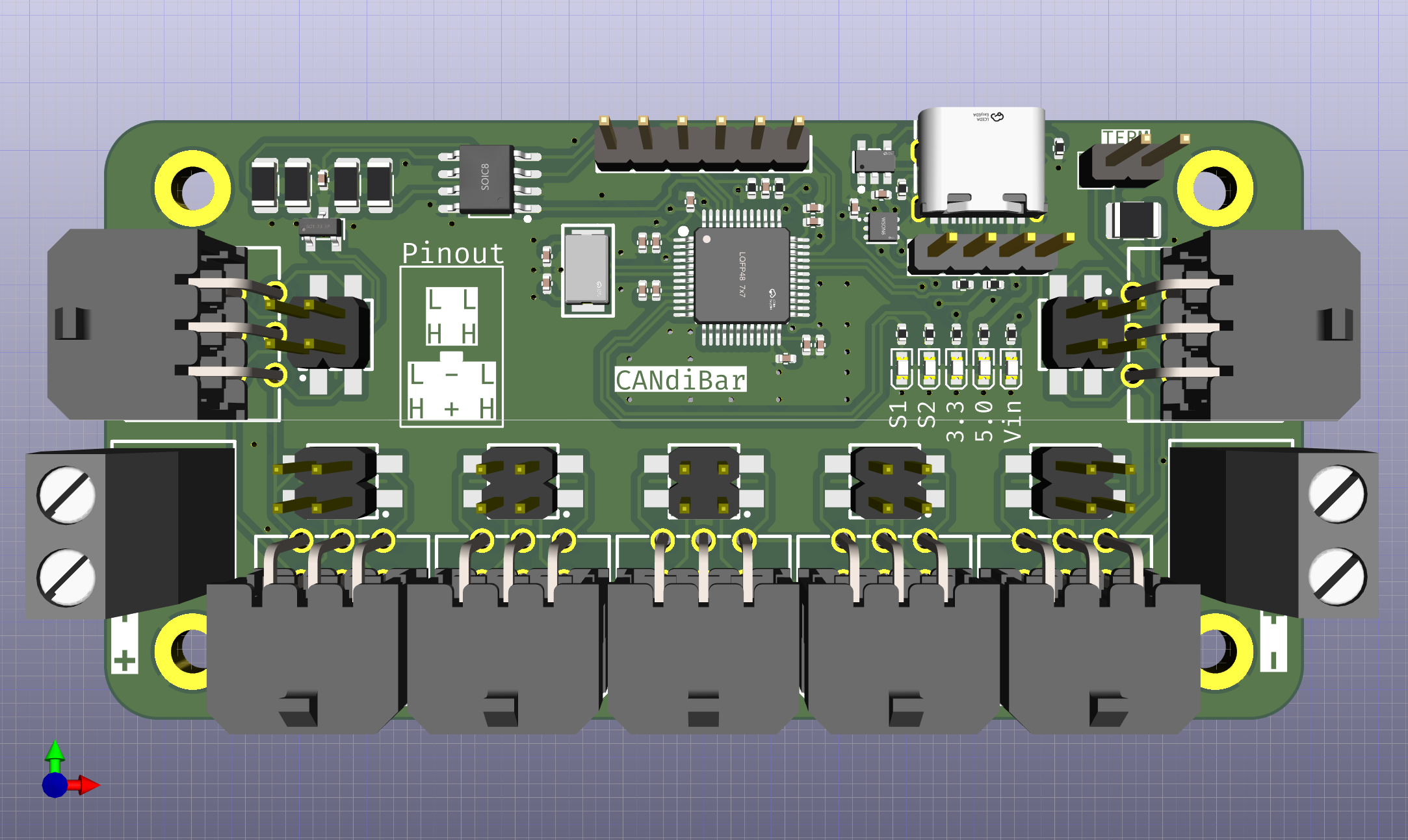
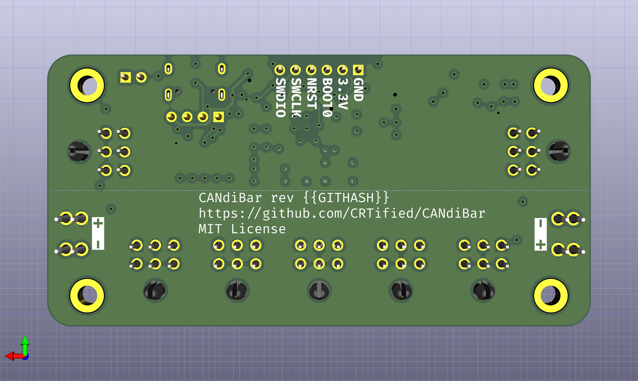
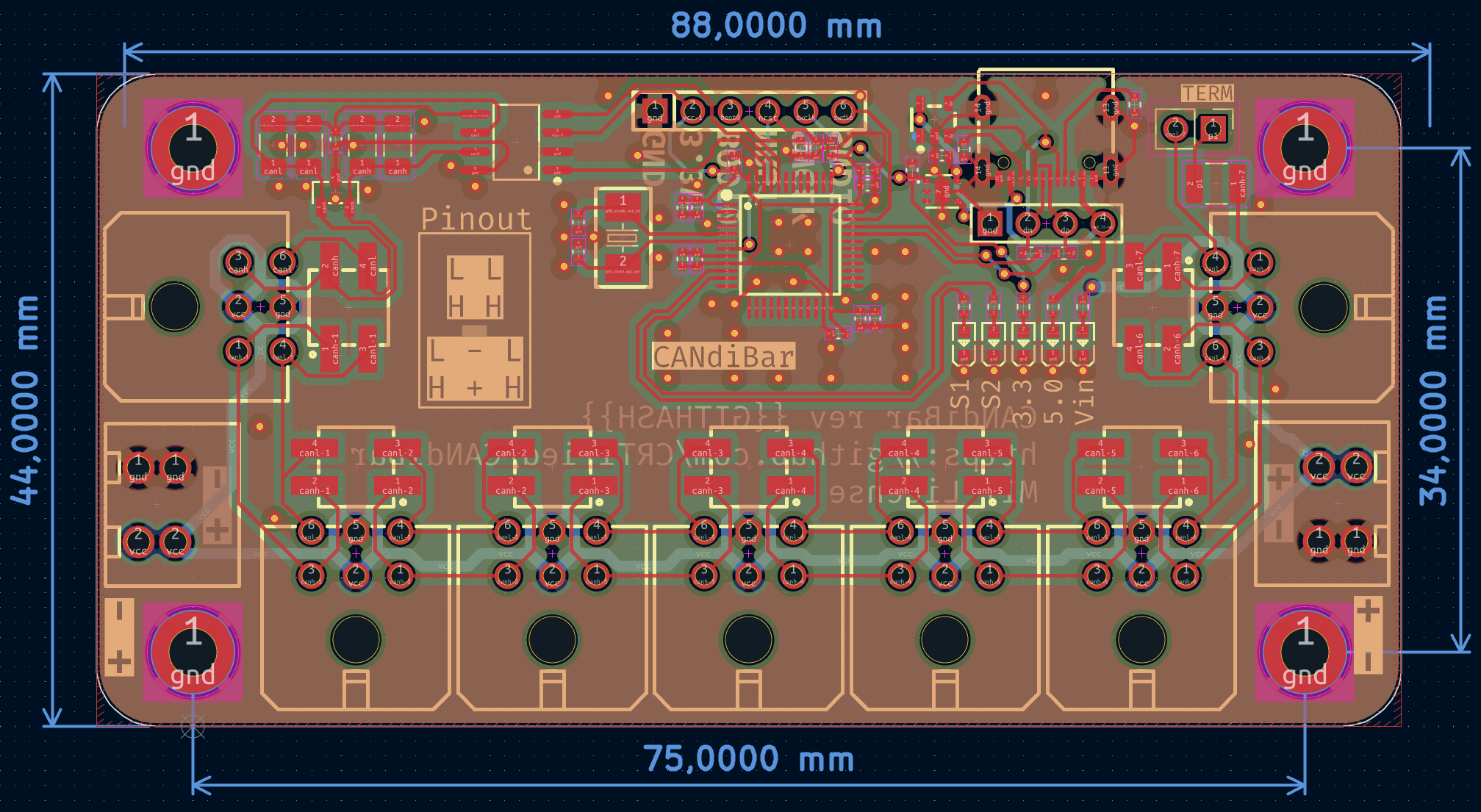
This repository aims to contain a small CAN bus and power distribution board. However, I wanted to avoid making all devices connected by a stub.
Properties:
I wanted to try atopile and a simple distribution board seemed like a great fit to test the whole design process.
I also wanted to have a sane piece of hardware for simplifying the wiring in my 3D printer, as the Voron v0.2r1 gets pretty crowded when using more than two MCUs.
| Qty | Value | Footprint | References |
|---|---|---|---|
| 8 | 16V 100nF X7R ±10% 0402 Multilayer Ceramic Capacitors MLCC - SMD/SMT ROHS | lib:C0402 | C6, C7, C8, C9, C10, C11, C13, C16 |
| 7 | ? | lib:CONN-TH_43045-0600 | J1, J2, J3, J4, J5, J6, J7 |
| 7 | ? | lib:HDR-SMD_4P-P2.54-V-M-R2-C2-LS7.5 | JP1, JP2, JP3, JP4, JP5, JP6, JP7 |
| 5 | 250mW Thick Film Resistors 200V ±100ppm/℃ ±1% 120Ω 1206 Chip Resistor - Surface Mount ROHS | lib:R1206 | R7, R8, R9, R10, R16 |
| 5 | ? | lib:LED0603-RD | U10, U11, U12, U19, U20 |
| 4 | ? | lib:MountingHole_3.2mm_M3_DIN965_Pad | U1, U2, U3, U4 |
| 3 | 10V 4.7uF X5R ±20% 0402 Multilayer Ceramic Capacitors MLCC - SMD/SMT ROHS | lib:C0402 | C3, C4, C5 |
| 3 | 62.5mW Thick Film Resistors 50V ±100ppm/℃ ±1% 10kΩ 0402 Chip Resistor - Surface Mount ROHS | lib:R0402 | R4, R6, R15 |
| 3 | 62.5mW Thick Film Resistors 50V ±100ppm/℃ ±1% 510Ω 0402 Chip Resistor - Surface Mount ROHS | lib:R0402 | R5, R13, R14 |
| 2 | 25V 1uF X5R ±10% 0402 Multilayer Ceramic Capacitors MLCC - SMD/SMT ROHS | lib:C0402 | C1, C2 |
| 2 | 50V 22pF C0G ±5% 0402 Multilayer Ceramic Capacitors MLCC - SMD/SMT ROHS | lib:C0402 | C14, C15 |
| 2 | 62.5mW Thick Film Resistors 50V ±1% ±100ppm/℃ 22Ω 0402 Chip Resistor - Surface Mount ROHS | lib:R0402 | R11, R12 |
| 2 | 62.5mW Thick Film Resistors 50V ±100ppm/℃ ±1% 5.1kΩ 0402 Chip Resistor - Surface Mount ROHS | lib:R0402 | R1, R2 |
| 2 | ? | lib:CONN-TH_978-Y-02 | U5, U6 |
| 1 | 50V 4.7nF X7R ±10% 0402 Multilayer Ceramic Capacitors MLCC - SMD/SMT ROHS | lib:C0402 | C12 |
| 1 | 62.5mW Thick Film Resistors 50V ±100ppm/℃ ±1% 1kΩ 0402 Chip Resistor - Surface Mount ROHS | lib:R0402 | R3 |
| 1 | ? | lib:SOT-23-5_L2.9-W1.6-P0.95-LS2.8-BR | U8 |
| 1 | ? | lib:USB-C-SMD_TYPE-C-6PIN-2MD-073 | U7 |
| 1 | ? | lib:CRYSTAL-SMD_L5.0-W3.2 | U18 |
| 1 | ? | lib:HDR-TH_4P-P2.54-V-M-1 | U9 |
| 1 | ? | lib:WSON-6_L2.0-W2.0-P0.65-TL-EP | U13 |
| 1 | ? | lib:PinHeader_1x02_P2.54mm_Vertical | JP8 |
| 1 | ? | lib:SOIC-8_L4.9-W3.9-P1.27-LS6.0-BL | U16 |
| 1 | ? | lib:HDR-TH_6P-P2.54-V-M-A | U15 |
| 1 | ? | lib:LQFP-48_L7.0-W7.0-P0.50-LS9.0-BL | U14 |
| 1 | ? | lib:SOT-23-3_L2.9-W1.3-P1.90-LS2.4-BR | U17 |
It measures 88 × 44 mm and has 4 copper layers, 1.6 mm thick.
67 parts. The full list of its parts is on this page, with links to each part's symbol and footprint where PCBKit's library has them.
From the CRTified/CANdiBar repository on GitHub, at the commit this page was made from: the board is elec/layout/default/candi-bar.kicad_pcb and its schematic elec/layout/default/candi-bar.kicad_sch. PCBKit opens the board in the browser, with nothing to install.
Its repository publishes it under the MIT licence: you may reuse it on that licence's terms (keep the author's notice, and for a copyleft licence share your changes alike).
loxodes/vna
Under development open hardware microwave vector network analyzer

deltabeard/DBGC
A Game Boy cartridge using the Raspberry Pi RP2040 with RTC and MBC support.


mirdej/synkie
The Synkie is a modular open source analog video processor, developed by Michael Egger, Max Egger and Flo Kaufmann

calithameridi/corevus
High-flexibility, low-cost mechatronics controller for 3D printers


LIV2/RIDE
To add the A0 Bonus RAM to the system you will need to use the addram command included in the RIDE-Software adf/lha found under Releases.
