4 layers318.4 × 124.5 mm

 LIV2/RIDE17
To add the A0 Bonus RAM to the system you will need to use the addram command included in the RIDE-Software adf/lha found under Releases.
RIDE is an open-source printed circuit board by LIV2, from the LIV2/RIDE repository on GitHub. It is a 4-layer board of 82.3 × 37.2 mm with 67 parts on 172 nets, routed with 1,812 tracks and 169 vias.
It is built around the 74HCT245, 74LVC245AD and W9812G6KH-6. Its parts include 26 capacitors, 21 resistors, 9 ICs, 4 connectors and 1 diode. It belongs with the FPGA and CPLD boards of this library.


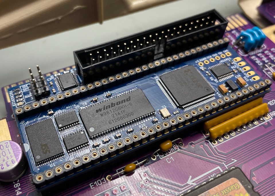
Compatible with Kickstart 1.3 and up.
IDE Off: Close to disable IDE
RAM1/RAM2: Autoconfig RAM configuration
| RAM1 | RAM2 | Size |
|---|---|---|
| Open | Open | 8 MB |
| Closed | Open | 4 MB |
| Open | Closed | 2 MB |
| Closed | Closed | Disable |
The A0 Bonus RAM is not automatically picked up by kickstart and needs to be added using one of the included utilities.
Note that the addmem command from Aminet will NOT work - the memory is not enabled until a specific RIDE register is set to enable it
To add the A0 Bonus RAM to the system you will need to use the addram command included in the RIDE-Software adf/lha found under Releases.
Alternatively you can add the bootrom module to a custom kickstart so that this is done automatically at every boot.
Program the CPLD using the relevant .jed file below (Right-click, Save as)
| Model | File |
|---|---|
| A500(+) A1000 A2000 | RIDE.jed |
| CDTV | RIDE-CDTV.jed |
You can find instructions on how to do that here
The IDE ROM can be programmed by booting from the latest lide-update.adf here.
Download the latest Gerbers.zip from the latest release listed on the right-hand side of this page.
Also included in the release are the placement and bom files needed for JLCPCB's assembly service
This PCB has been designed to JLCPCB's 4-layer capabilities so I recommend ordering from them
The release files include the relevant BOM and CPL files for JLCPCB's Assembly service
You can use the following options:
Note:
Thanks to SukkoPera for supporting my early IDE prototype.

This project is licensed under the GPL-2.0 only license
| Qty | Value | Footprint | References |
|---|---|---|---|
| 21 | 0.1u | Capacitor_SMD:C_0603_1608Metric | C1, C2, C3, C4, C10, C11, C12, C13, C16, C17, C18, C19, C20, C22, C23, C24 +5 |
| 8 | 10K | Resistor_SMD:R_0603_1608Metric | R4, R5, R8, R10, R11, R15, R16, R17 |
| 7 | 33 | Resistor_SMD:R_0603_1608Metric | R6, R7, R9, R13, R14, R18, R19 |
| 3 | 10k | Resistor_SMD:R_0603_1608Metric | R1, R2, R3 |
| 3 | 150 | Resistor_SMD:R_0603_1608Metric | R12, R20, R21 |
| 3 | 74HCT245 | Package_SO:TSSOP-20_4.4x6.5mm_P0.65mm | U4, U8, U9 |
| 2 | 10u | Capacitor_Tantalum_SMD:CP_EIA-3216-18_Kemet-A | C14, C15 |
| 2 | 10u | Capacitor_SMD:C_0805_2012Metric_Pad1.18x1.45mm_HandSolder | C21, C25 |
| 2 | 74LVC245 | Package_SO:TSSOP-20_4.4x6.5mm_P0.65mm | U2, U3 |
| 1 | 47uF | Capacitor_Tantalum_SMD:CP_EIA-3216-18_Kemet-A_Pad1.58x1.35mm_HandSolder | C26 |
| 1 | 50MHz | Oscillator:Oscillator_SMD_Abracon_ASE-4Pin_3.2x2.5mm | X1 |
| 1 | AMIGA | Package_DIP:DIP-64_W22.86mm | AMIGA1 |
| 1 | AZ1117-3.3 | Package_TO_SOT_SMD:SOT-89-3 | U7 |
| 1 | Conn_01x05_Pin | Connector_PinHeader_2.54mm:PinHeader_1x05_P2.54mm_Vertical | J3 |
| 1 | Conn_01x06_Male | Connector_PinHeader_2.54mm:PinHeader_1x06_P2.54mm_Vertical | J2 |
| 1 | Conn_02x03_Odd_Even | Connector_PinHeader_2.54mm:PinHeader_2x03_P2.54mm_Vertical | J4 |
| 1 | G*** | kibuzzard-667ABBF2 | kibuzzard-3 |
| 1 | G*** | kibuzzard-667ABBFF | kibuzzard-1 |
| 1 | G*** | kibuzzard-667CDE38 | kibuzzard-2 |
| 1 | IDE | Connector_IDC:IDC-Header_2x20_P2.54mm_Vertical | J1 |
| 1 | LED | LED_SMD:LED_0603_1608Metric | D1 |
| 1 | Polyfuse 500mA Hold | Fuse:Fuse_1206_3216Metric_Pad1.42x1.75mm_HandSolder | F1 |
| 1 | SST39SF010 | Package_SO:TSOP-I-32_11.8x8mm_P0.5mm | U1 |
| 1 | W9812G6KH-6 | Package_SO:TSOP-II-54_22.2x10.16mm_P0.8mm | U5 |
| 1 | XC95144XL-TQ100 | Package_QFP:TQFP-100_14x14mm_P0.5mm | U6 |
It measures 82.3 × 37.2 mm and has 4 copper layers, 1.6 mm thick.
67 parts, built around the 74HCT245, 74LVC245AD and W9812G6KH-6. The full list of its parts is on this page, with links to each part's symbol and footprint where PCBKit's library has them.
From the LIV2/RIDE repository on GitHub, at the commit this page was made from: the board is Kicad/RIDE.kicad_pcb and its schematic Kicad/CPLD.kicad_sch. PCBKit opens the board in the browser, with nothing to install.
Its repository states no licence, so its author keeps all rights: ask LIV2 before reusing the design.

lfantoniosi/CoCoTANG
CoCoTANG upgrades the Radio Shack/Tandy Color Computer with a Tang Nano 20K FPGA board and CoCo 3 video and memory features.

pauldevine/user_port_v9k
Using a raspberry pico connected to the User or Control Port of the Victor 9000 as a hard drive.


