4 layers214 × 142.6 mm
Unmechanical sweepish
ebastler/UnMechanical
Capacitive touch keyboard running QMK firmware
168 parts13CERN-OHL-P-2.0

 crosbee/h2track
An telemetry tracker designed for an ESP32 with an easy api to integrate trackers and inputs with accompanying software to view live data and to pass inputs.
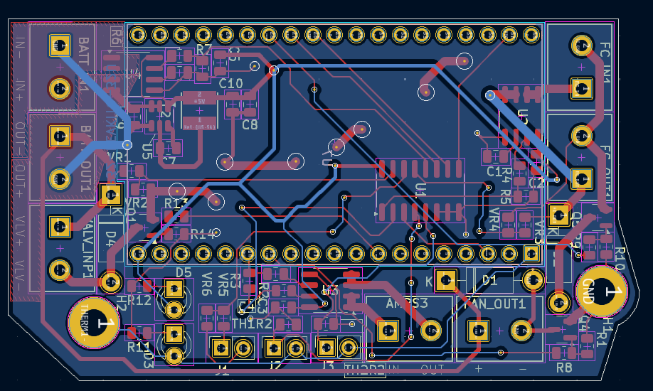
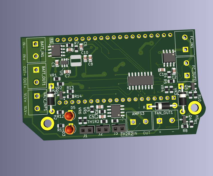
Car tracker circuit is an open-source printed circuit board by crosbee, from the crosbee/h2track repository on GitHub. It is a 2-layer board of 42.1 × 73.3 mm with 59 parts on 71 nets, routed with 394 tracks and 36 vias.
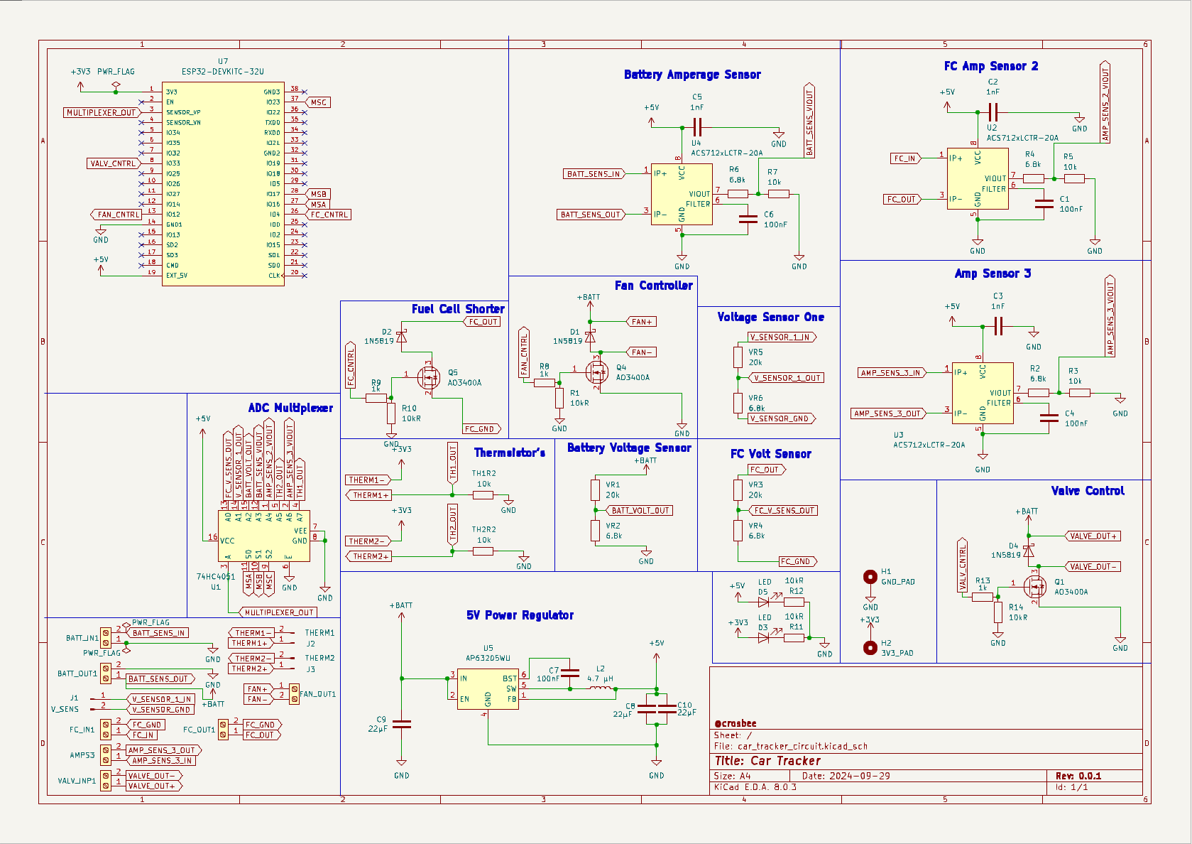
It is built around the ESP32-DEVKITC-32UE, AP63205WU and 74HC4051, with the AO3400A among its other parts. Its parts include 19 resistors, 10 capacitors, 6 ICs, 5 diodes and 3 transistors. It belongs with the ESP32 boards of this library.


An telemetry tracker designed for an ESP32 with an easy api to integrate trackers and inputs with accompanying software to view live data and to pass inputs. Built for use to track and adjust hydrogen cars remotely however can be easily adjusted for any other purpose.
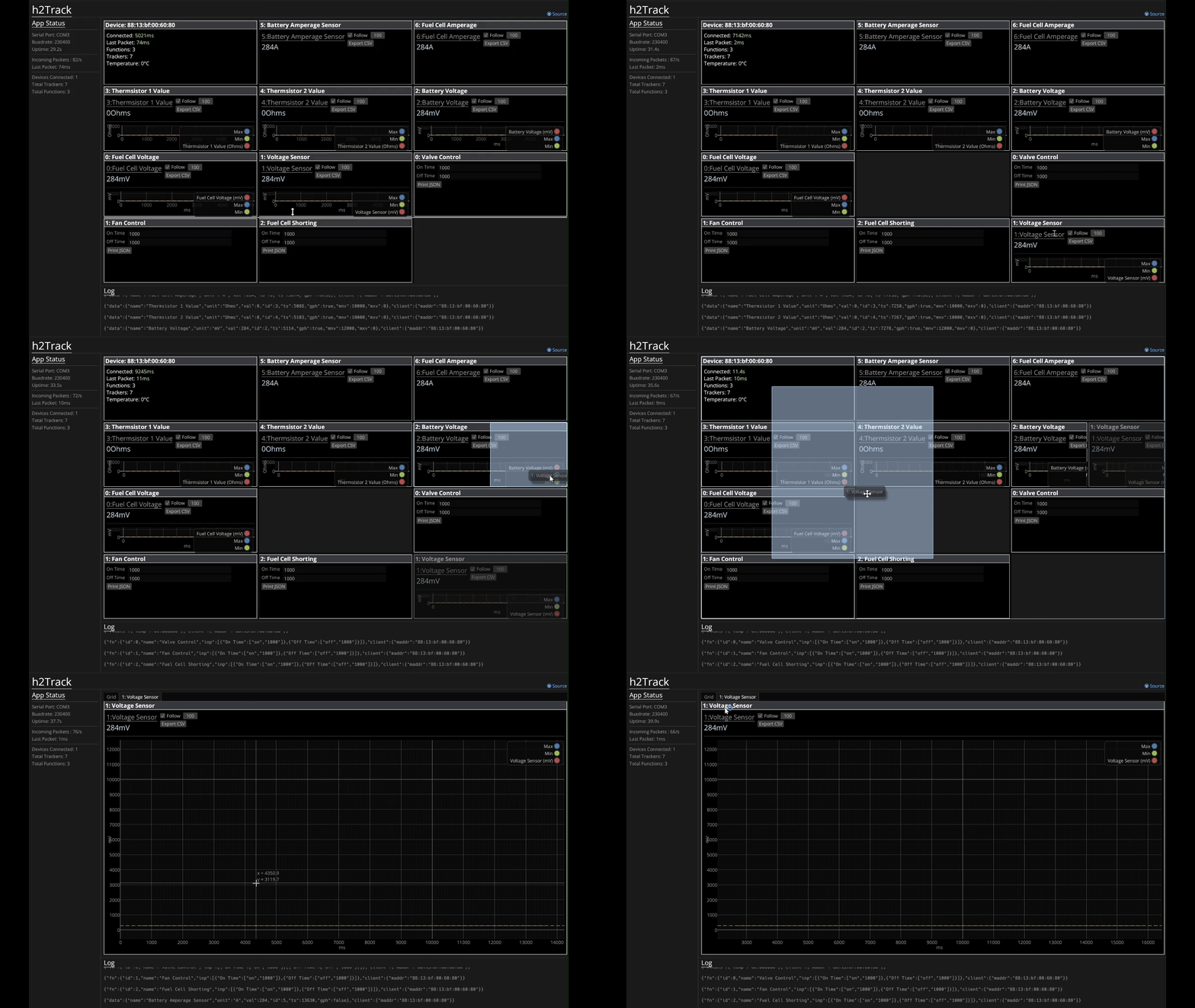
To Flash
pio run -e receiver -t uploadpio run -e [TYPE] -t uploadcargo build --releaseThe software for the gui does not need to be modified, as it dynamically creates the trackers based on the info sent by the receiver. To track/adjust something else, create the necessary functions regarding info of the tracker and updating and transmitting the tracker/function.
|
|
|
The PCB and circuit were made in KiCAD. The current version is the second prototype and has not been tested. The PCB is designed specifically for a tracking hydrogen cars with the following trackers/features:
| Qty | Value | Footprint | References |
|---|---|---|---|
| 7 | Screw_Terminal_01x02 | KF301-2P:HANDSON_KF301-2P | AMPS3, BATT_IN1, BATT_OUT1, FAN_OUT1, FC_IN1, FC_OUT1, VALV_INP1 |
| 6 | 6.8k | Resistor_SMD:R_0805_2012Metric | R2, R4, R6, VR2, VR4, VR6 |
| 5 | 10k | Resistor_SMD:R_0805_2012Metric | R3, R5, R7, TH1R2, TH2R2 |
| 5 | 10kR | Resistor_SMD:R_0805_2012Metric | R1, R10, R11, R12, R14 |
| 4 | 100nF | Capacitor_SMD:C_0805_2012Metric | C1, C4, C6, C7 |
| 3 | 1N5819 | Diode_THT:D_DO-41_SOD81_P10.16mm_Horizontal | D1, D2, D4 |
| 3 | 1k | Resistor_SMD:R_0805_2012Metric | R8, R9, R13 |
| 3 | 1nF | Capacitor_SMD:C_0805_2012Metric | C2, C3, C5 |
| 3 | 20k | Resistor_SMD:R_0805_2012Metric | VR1, VR3, VR5 |
| 3 | 22µF | Capacitor_SMD:C_0805_2012Metric | C8, C9, C10 |
| 3 | ACS712xLCTR-20A | Package_SO:SOIC-8_3.9x4.9mm_P1.27mm | U2, U3, U4 |
| 3 | AO3400A | Package_TO_SOT_SMD:SOT-23 | Q1, Q4, Q5 |
| 2 | LED | LED_THT:LED_D3.0mm | D3, D5 |
| 1 | 3V3_PAD | MountingHole:MountingHole_3.2mm_M3_DIN965_Pad | H2 |
| 1 | 4.7 µH | easyeda2kicad:IND-SMD_L4.0-W4.0_FNR40XXS | L2 |
| 1 | 74HC4051 | Package_SO:SOP-16_3.9x9.9mm_P1.27mm | U1 |
| 1 | AP63205WU | Package_TO_SOT_SMD:TSOT-23-6 | U5 |
| 1 | ESP32-DEVKITC-32U | ESP32-DEVKITC-32U:MODULE_ESP32-DEVKITC-32U | U7 |
| 1 | GND_PAD | MountingHole:MountingHole_3.2mm_M3_DIN965_Pad | H1 |
| 1 | THERM1 | Connector_PinSocket_2.54mm:PinSocket_1x02_P2.54mm_Vertical | J2 |
| 1 | THERM2 | Connector_PinSocket_2.54mm:PinSocket_1x02_P2.54mm_Vertical | J3 |
| 1 | V_SENS | Connector_PinSocket_2.54mm:PinSocket_1x02_P2.54mm_Vertical | J1 |
ebastler/UnMechanical
Capacitive touch keyboard running QMK firmware


Matyas604/Security-Alarm-Panel
Home Assistant Smart Home Alarm Control Panel with fingerprint reader, NFC/RFID card reader, motion radar, and touchscreen TFT display. It can control your smart home, not just your home security system.

Quard/MLight
MLight is a compact, all-in-one control board designed to manage auxiliary tools for soldering equipment
It measures 42.1 × 73.3 mm and has 2 copper layers, 1.6 mm thick.
59 parts, built around the ESP32-DEVKITC-32UE, AP63205WU, 74HC4051 and AO3400A. The full list of its parts is on this page, with links to each part's symbol and footprint where PCBKit's library has them.
From the crosbee/h2track repository on GitHub, at the commit this page was made from: the board is circuit/car_tracker_circuit.kicad_pcb and its schematic circuit/car_tracker_circuit.kicad_sch. PCBKit opens the board in the browser, with nothing to install.
Its repository states no licence, so its author keeps all rights: ask crosbee before reusing the design.