
2 layers148 × 81 mm
Communicator pcb
Hack-a-Day/2025-Communicator_Badge
The 2025 Hackaday Supercon RF Communicator Badge
58 parts107MIT

 crash8229/LED-Cubes
A repo to hold my LED cube related projects
5x5 LED Cube Driver is an open-source printed circuit board by crash8229, from the crash8229/LED-Cubes repository on GitHub, published under the GPL-3.0 licence. It is a 2-layer board of 88.9 × 81.3 mm with 46 parts on 45 nets, routed with 224 tracks and 11 vias.
It is built around the DMG2305UX. Its parts include 25 diodes, 8 resistors, 5 transistors, 3 connectors and 2 ICs.
A repo to hold my LED cube related projects.
Getting Started Guide: https://datasheets.raspberrypi.com/pico/getting-started-with-pico.pdf.
Requires the Pico C++ SDK. Instructions are provided in the Getting Started Guide.
Make sure the PICO_SDK_PATH environment variable is set. You may need to set the variable in your IDE as well.
If using the Picoprobe for development.
Refer to the Appendix A: Using Picoprobe section of the Getting Started Guide to set things up.
If using the Pi Debug Probe for development. Refer to this webpage to set things up: https://www.raspberrypi.com/documentation/microcontrollers/debug-probe.html
I use openocd and have created config files under program/rpi_pico_driver/openocd_targets for using the Picoprobe and Pi Debug Probe.
These simply combined the needed config files that came with openocd for ease of use.
You will need set the environment variables used by CMake.
This is done by going to File > Settings... > Build, Exexution, Deployment > CMake.
With a profile selected, add variables to the Environment field.
The only one currently needed is the PICO_SDK_PATH variable that points to the location of the Pico SDK.
There are 2 ways to set up the Run/Debug configurations: OpenOCD Download & Run or Embedded GDB Server
This is the preferred way as it allows one to run or debug the program.
If using the Picoprobe, create an OpenOCD Download & Run configuration and configure as shown below: 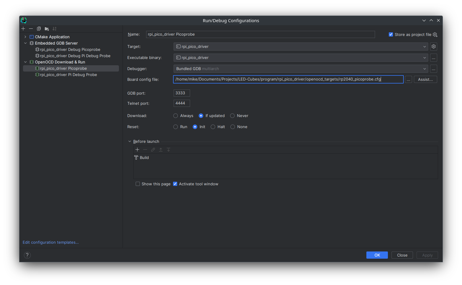 If using the Pi Debug Probe, create an
OpenOCD Download & Run configuration and configure as shown below: 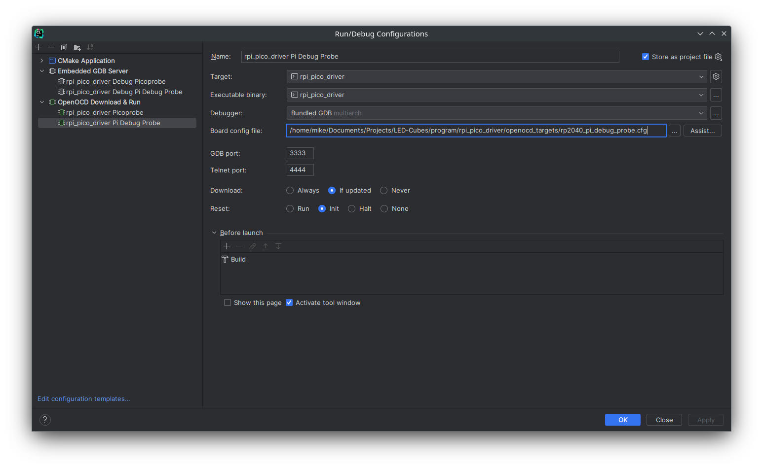
This way only allows one to debug the program.
If using the Picoprobe, create an Embedded GDB Server configuration and configure as shown below: 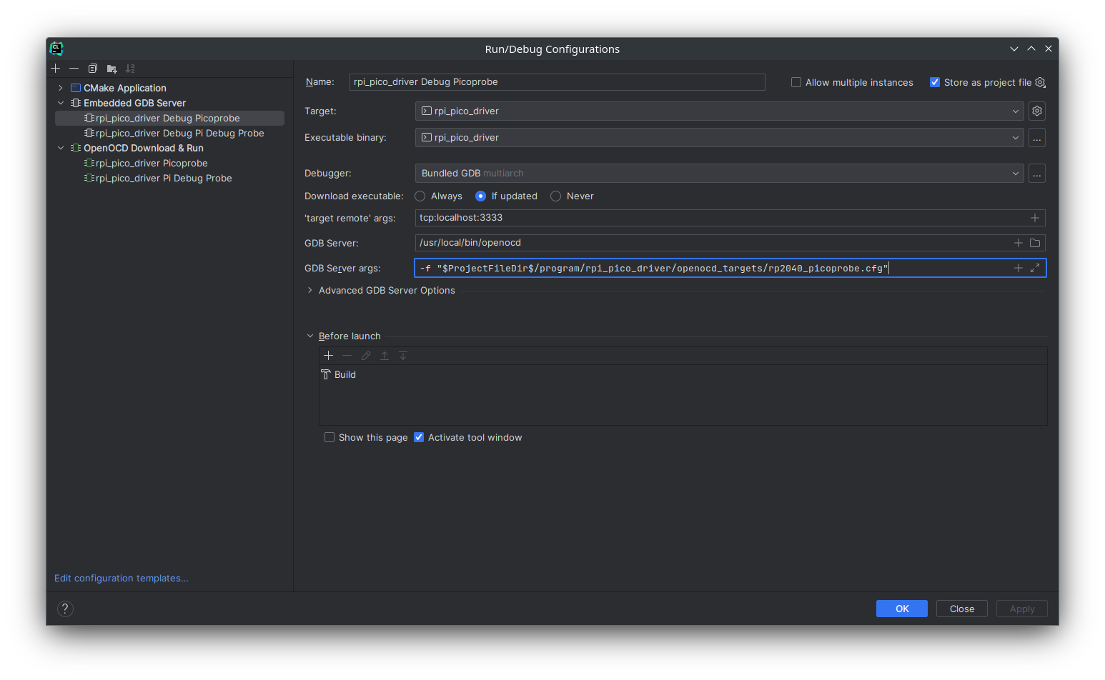 If using the Pi Debug Probe, create an
Embedded GDB Server configuration and configure as shown below: 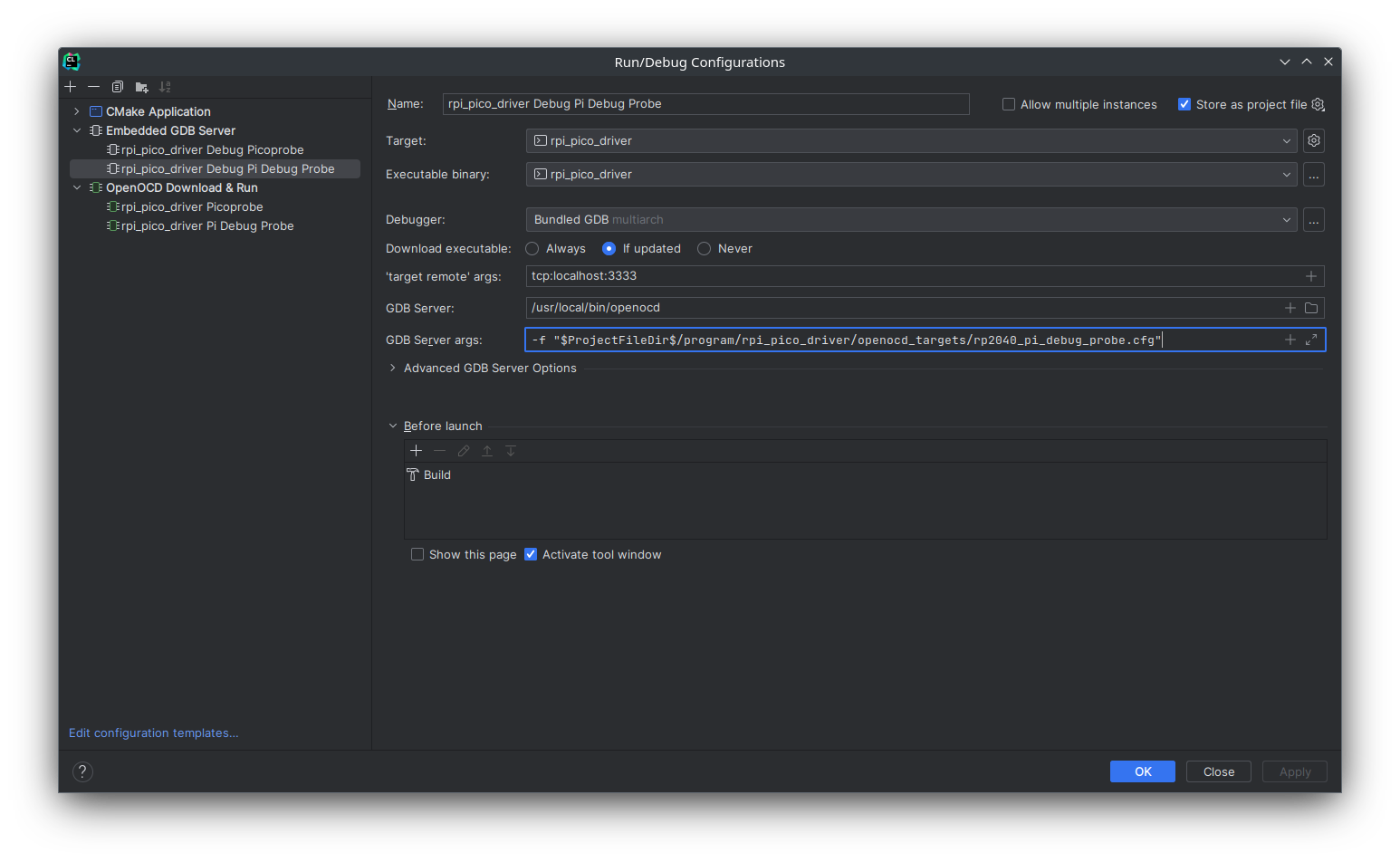
WIP (Need to get it working)
| Qty | Value | Footprint | References |
|---|---|---|---|
| 25 | LED | Connector_Pin:Pin_D1.0mm_L10.0mm | D1, D2, D10, D11, D12, D13, D14, D15, D16, D17, D18, D19, D20, D21, D22, D23 +9 |
| 6 | 4.7K | Resistor_SMD:R_0603_1608Metric | R3, R4, R5, R6, R7, R8 |
| 5 | DMG2305UX | Package_TO_SOT_SMD:SOT-23 | Q1, Q2, Q3, Q4, Q5 |
| 2 | 2.7K | Resistor_SMD:R_0603_1608Metric | R1, R2 |
| 2 | TLC5940NT | Package_DIP:DIP-28_W7.62mm | U1, U2 |
| 1 | Arduino | Connector_PinHeader_2.00mm:PinHeader_1x07_P2.00mm_Vertical | J1 |
| 1 | Layers | Connector_PinHeader_2.00mm:PinHeader_1x05_P2.00mm_Vertical | J3 |
| 1 | Power | Connector_PinHeader_2.00mm:PinHeader_1x02_P2.00mm_Vertical | J2 |
The 43 most common of 46 parts.
Hack-a-Day/2025-Communicator_Badge
The 2025 Hackaday Supercon RF Communicator Badge


hasenbanck/heteromycin
A 3D printer board using a powerfull STM32 MCU, TMC5160/TMC2160 driver and a Raspberry Pi or compatible SBC


m-labs/ionpak
A modern, low-cost universal controller for hot-cathode ionization vacuum gauges. (WIP)

It measures 88.9 × 81.3 mm and has 2 copper layers, 1.6 mm thick.
46 parts, built around the DMG2305UX. The full list of its parts is on this page, with links to each part's symbol and footprint where PCBKit's library has them.
From the crash8229/LED-Cubes repository on GitHub, at the commit this page was made from: the board is schematic/5x5_LED_Cube/5x5_LED_Cube_Driver.kicad_pcb and its schematic schematic/5x5_LED_Cube/5x5_LED_Cube_Driver.kicad_sch. PCBKit opens the board in the browser, with nothing to install.
Its repository publishes it under the GPL-3.0 licence: you may reuse it on that licence's terms (keep the author's notice, and for a copyleft licence share your changes alike).