2 layers18.1 × 33.3 mm
 cotty52/Mouse1
Custom mouse using PMW3389 sensor and nRF52840 microcontroller
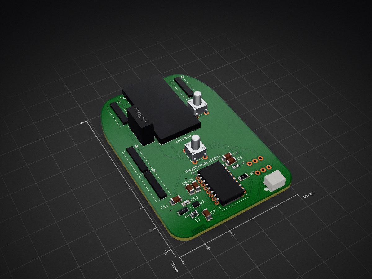
Mouse Project is an open-source printed circuit board by cotty52, from the cotty52/Mouse repository on GitHub. It is a 2-layer board of 50 × 73 mm with 28 parts on 43 nets, routed with 136 tracks and 4 vias.
It is built around the TPS62821DLCR and B2B-PH-K-S. Its parts include 11 capacitors, 4 switches, 3 resistors, 2 ICs and 1 connector. It belongs with the nRF52 and nRF5x boards of this library.


This project contains software and hardware designs for a custom wireless mouse. This is an initial prototype intended for me to learn about hardware design and embedded software development. I combined hardware and software files into one repository for easier management. As of 2026-04-21, the design supports basic mouse functionality, including movement, button presses, and scrolling, and is powered by a 3.7V Li-ion battery, rechargeable via USB-C.
Mouse/
├── Documents/        # Datasheets, bootloader UF2, 3D models
├── Guide/
│   └── README.md     # New machine setup guide
├── KiCad/            # PCB schematics and layout
└── Software/
    ├── PROJECT_GUIDE.md  # Architecture, task tracking, module reference
    └── ...
Documents contains datasheets, reference layouts, and documentation for the nRF Connect SDK and Zephyr project.Guide contains the new machine setup guide (Guide/README.md) and dated snapshots of known-good board/config files.KiCad contains the KiCad project files for the PCB design (schematics, PCB layout, Gerber files).Software contains firmware source, board definitions, and configuration files. See Software/PROJECT_GUIDE.md for details.The hardware design is based on the nRF52840 because of its popularity/availability, built in Bluetooth, low power consumption, and integration with the nRF SDK for software development. The PCB was designed using KiCad and currently relies on a nRF52840 nice!nano microcontroller for higher level development in the early stages. The microcontroller includes a USB-C port for charging and firmware flashing, a charging protection circuit, and enough GPIO for this project. The design also includes a PMW3389 optical sensor for mouse movement, which is supported by the nRF SDK and Zephyr.
| Full | Front | Back |
|---|---|---|
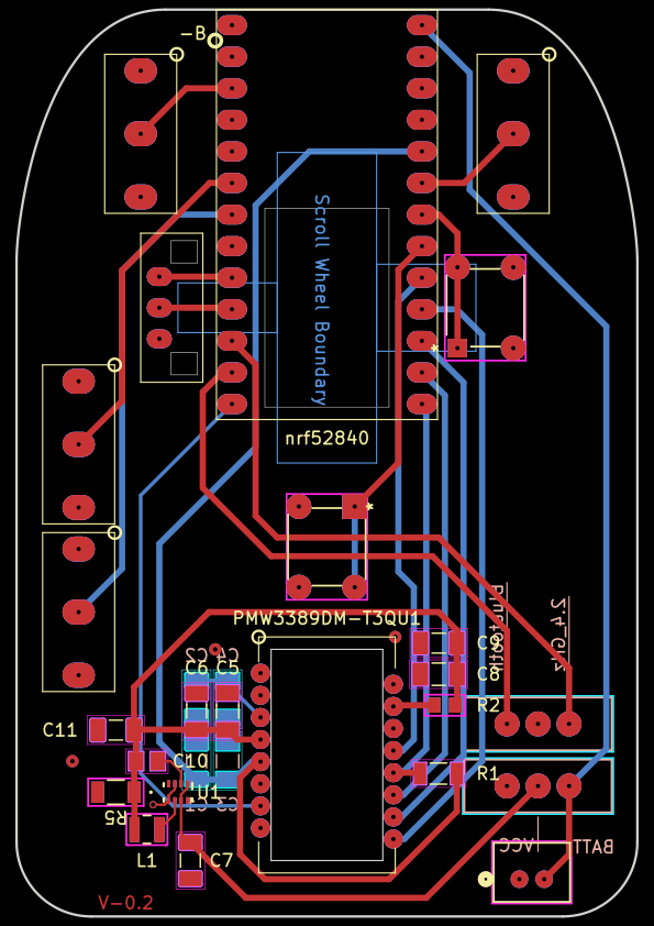 | 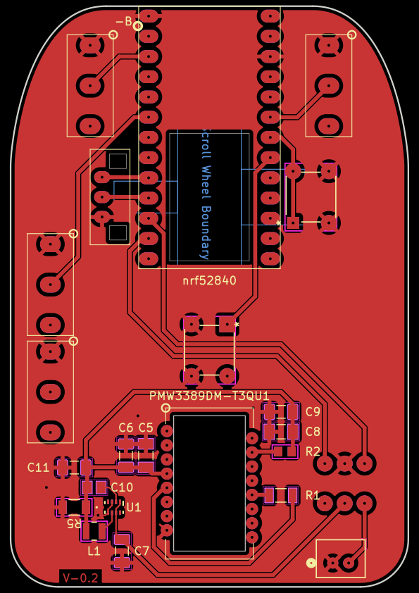 | 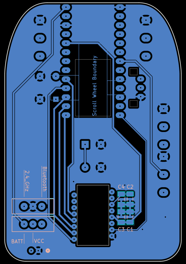 |
The software is developed using the nRF Connect SDK, which is based on the Zephyr RTOS. The nRF Connect VS Code extension is used for development, which provides a convenient interface for firmware development. The base structure is copied directly from the nRF Desktop sample project, which provides a good starting point for developing a Bluetooth mouse. The sample provides support for Bluetooth connectivity, mouse movement, button presses, and scrolling out of the box, with additional features available to be toggled on/off using the Kconfig GUI. The sample also provides sample mouse configurations as well as a PMW3360 driver, which is similar to the PMW3389. These files serve as a reference for the development of custom hardware and application files for the custom mouse.
As of 2026-04-27 there are a couple major issues. The primary issue is the nice!nano board itself. While it was a good microcontroller to get started with this project and to learn about the basics, it was sometimes difficult to work with. Even though there are SWD pads on the back of the board, I could not get it to work with my nRF52840-DK. I also could not get bluetooth to work on the nice!nano, which is why I switched to the nRF52840-dongle for the most recent development. The dongle is meant to be a receiver, but it has enough gpio to connect everything; and since it is a nordic product, development was much easier.
The second problem was with the pmw3389 sensor. I have not figured out why it was not working with my PCB, but I was able to get it working with a breakout board. A multimeter showed that the voltage at the VDD pin was not stable and would start below 1.9V, then rise to above 1.9V. This leads me to believe my step-down circuit is wrong; either I got the calculations for the resistors and capacitors wrong, or the buck converter was not soldered properly. I used a microscope and the connections looked good, but it is very small so it's possible there is a cold solder joint or something else I missed.
The next step is to design the PCB without the nice!nano which will require using the nRF52840 SoC directly. This will involve further researching the nRF52840 for proper implementation as well as designing power management and charging circuits. I will also need to decide on whether to use an SoC with an included antenna or design one myself.
Becasue of the problems with the pmw3389, I will not use the TPS62821DLCR buck converter. I will probably use a linear step-down regulator instead, which will be less efficient but much simpler to implement.
On the software side, the next step is to develop custom application code for the mouse which will allow users to customize the behavior of the mouse, such as button mapping and sensitivity settings.
| Qty | Value | Footprint | References |
|---|---|---|---|
| 4 | 0.1uF | C1206C104K5RACTU:C1206C104K5RACTU | C3, C4, C5, C8 |
| 4 | 10uF | CL31A106KBHNNNE:CL31A106KBHNNNE | C1, C6, C9, C11 |
| 2 | 4.7uF | CL31B475KBHNNNE:CL31B475KBHNNNE | C2, C7 |
| 1 | 10k | RC1206FR_0710KL:RC1206FR-0710KL | R1 |
| 1 | 120pF | C0805C121J5GACTU:C0805C121J5GACTU | C10 |
| 1 | 13 | RC0805FR_0713RL:RC0805N_YAG | R2 |
| 1 | 330k | CRGCQ1206F330K:RES_CRGCQ1206F330K_TEC | R5 |
| 1 | 470nH | DFE252012P-R47M=P2:DFE252012P-1R0M=P2 | L1 |
| 1 | B2B-PH-K-S | B2B-PH-K-S:CONN2_B2B-PH-K-S_JST | J1 |
| 1 | DPI_Button | 1825910-6:SW4_1825910-B_TEC | SW4 |
| 1 | Left | Kailh_Switch:Kailh_Switch | Kailh_Switch1 |
| 1 | Power | EG1218:SW_1218_EWI | SW1 |
| 1 | Right | Kailh_Switch:Kailh_Switch | Kailh_Switch2 |
| 1 | Scroll_Button | 1825910-6:SW4_1825910-B_TEC | SW3 |
| 1 | Signal | EG1218:SW_1218_EWI | SW2 |
| 1 | TPS62821DLCR | TPS62821DLCR:TPS62821DLCR | U1 |
| 1 | TTC_Gold_Encoder | TTC_Gold_Encoder:TTC_Gold_Encoder | U2 |
| 1 | Thumb1 | Kailh_Switch:Kailh_Switch | Kailh_Switch3 |
| 1 | Thumb2 | Kailh_Switch:Kailh_Switch | Kailh_Switch4 |
| 1 | nrf52840 | nrf52840_promicro:nrf52840_promicro | NRF52840_ProMicro1 |
| 1 | pmw3389 | pmw3389dm-t3qu:pmw3389dm-t3qu | PMW3389DM-T3QU1 |
It measures 50 × 73 mm and has 2 copper layers, 1.6 mm thick.
28 parts, built around the TPS62821DLCR and B2B-PH-K-S. The full list of its parts is on this page, with links to each part's symbol and footprint where PCBKit's library has them.
From the cotty52/Mouse repository on GitHub, at the commit this page was made from: the board is KiCad/Mouse_Project.kicad_pcb and its schematic KiCad/Mouse_Project.kicad_sch. PCBKit opens the board in the browser, with nothing to install.
Its repository states no licence, so its author keeps all rights: ask cotty52 before reusing the design.


QuickLogic-Corp/quick-feather-dev-board
100% open source dev kit for EOS S3 MCU+eFPGA SoC supported by fully open source SDK and FPGA Toolchain

antmicro/quickfeather-dev-board
This project contains open hardware design files for the QuickFeather development board based on the QuickLogic EOS S3 Sensor Processing Platform.

wattnotions/povbot2
Look in 3dprint folder to find a 3mf file with the chassis , camera holder and wheels ready to print.

Xenii1642/USB-GC2
Meet the new generation of USB-C GameCube Power Board. Now compatible with both 12V and 15V chargers. Two voltages, twice the potential.

FeruzTopalov/spoke
Standalone LoRa-based real-time off-grid relative GPS navigation for group of up to 5 people. Improved version of LRNS Eleph

greigs/OpenBrickGB
Functional / Playable Lego Game Boy Electronics - PCB Design Files

Andresse2020/NovaDrone-Hardware
Complete electronic system design for a high-performance quadcopter drone, developed entirely from scratch. Includes power distribution, motor control, flight stabilization, sensor integration, and communication…
