4 layers72 × 141.7 mm
BRZ Breakout withCAN
jacky4566/BRZFRS_Breakout_withCAN
An inline ECU breakout board for the Subaru BRZ / Scion FR-S / Toyota 86 with a built-in CAN I/O module.
63 partsMIT

 corygrant/CANBoard53
Hardware - CAN enabled small input / output expansion board. Switch panels, steering wheel buttons/knobs, etc.
CANBoard is an open-source printed circuit board by corygrant, from the corygrant/CANBoard repository on GitHub, published under the MIT licence. It is a 4-layer board of 40 × 40 mm with 83 parts on 64 nets, routed with 440 tracks and 75 vias.
It is built around the STM32F303K8T6, MCP2562-H/P and LD1117S33CTR-HXY, with the DMN2004WK and NUP2105LT1G among its other parts. Its parts include 35 resistors, 22 capacitors, 5 connectors, 4 ICs and 4 transistors. It belongs with the STM32 boards of this library.


CANBoard is a simple CAN enabled IO board, specifically designed to be used in devices like steering wheels/button boxes/panels/etc.
If this project does help you in any way, I'd appreciate a message!
Please note that this product has been designed by a hobbyist, not a professional. It is intended for off-road and testing use only. Users should operate the product at their own discretion and risk. The designer explicitly disclaims any responsibility for damage or injury that may result from the use of this product.
DBC file can be found here
CAN Term : Soldering this jumper enables the 120 ohm terminating resistor across CANL/CANH
CAN ID Jumpers 1 and 2 : Not used by dingoFW. The base CAN ID (default 0x640) and bitrate are set with dingoConfig. When using multiple CANBoards on the same bus, give each one a different base ID in dingoConfig.
The jumpers were used by the old CANBoard_FW firmware:
| 1 | 2 | Base CAN ID (Hex) |
|---|---|---|
| Open | Open | 0x640 |
| Closed | Open | 0x650 |
| Open | Closed | 0x660 |
| Closed | Closed | 0x670 |
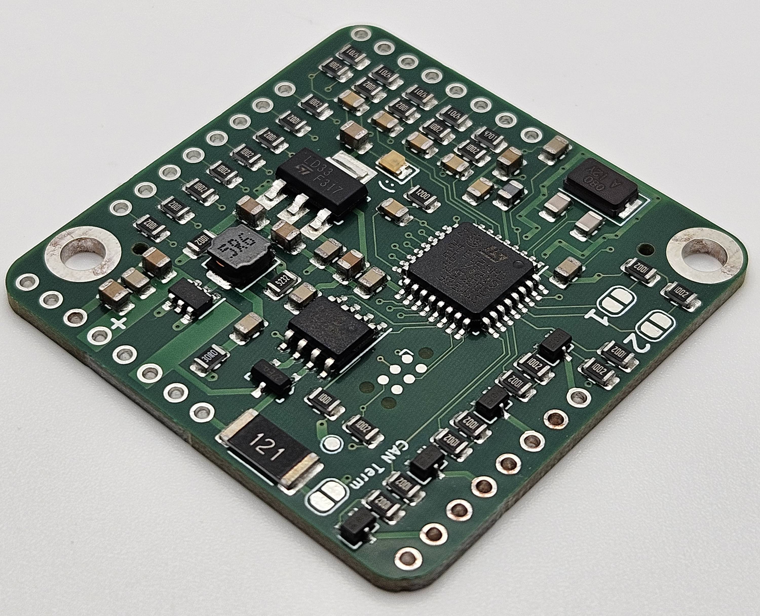
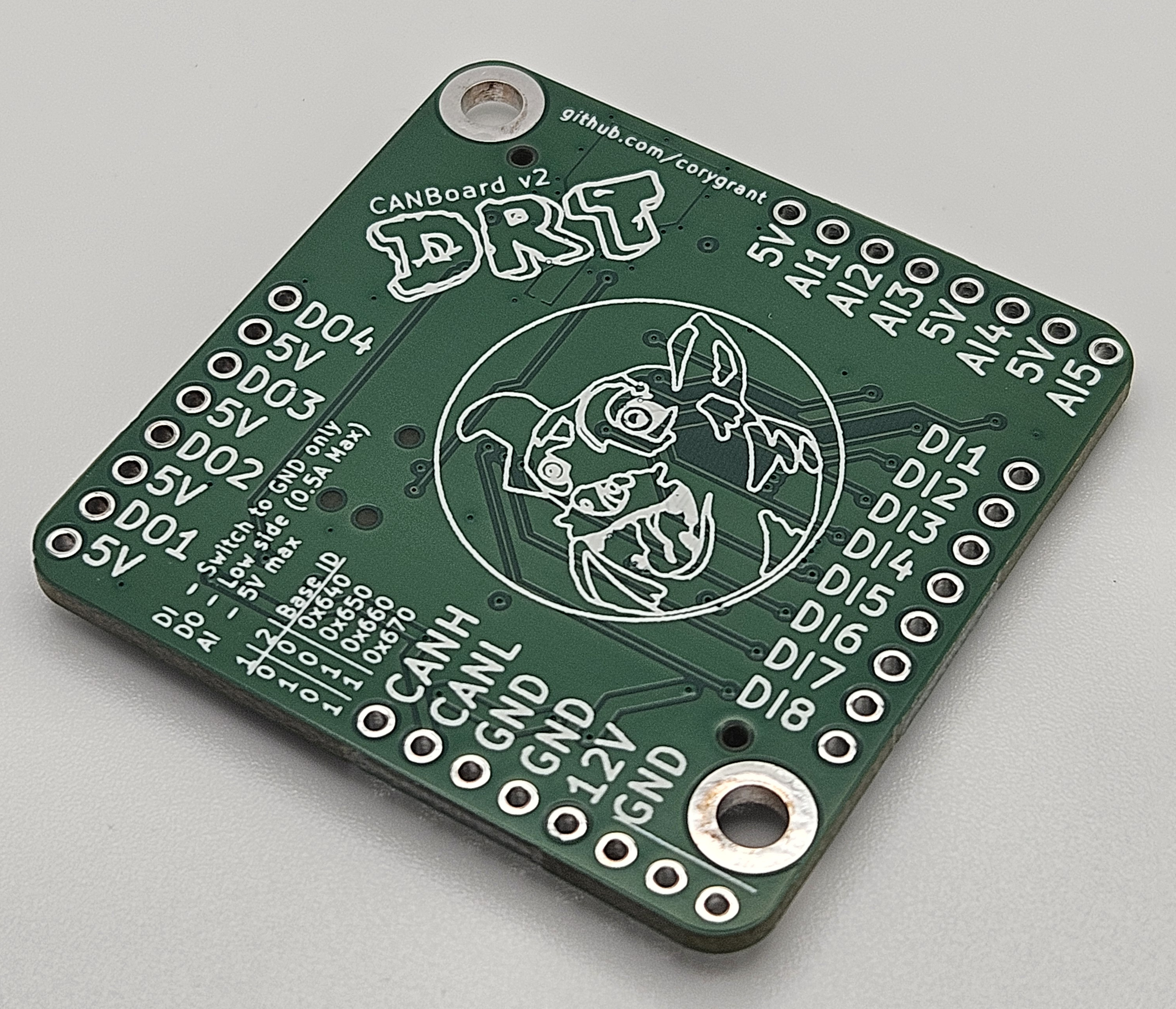
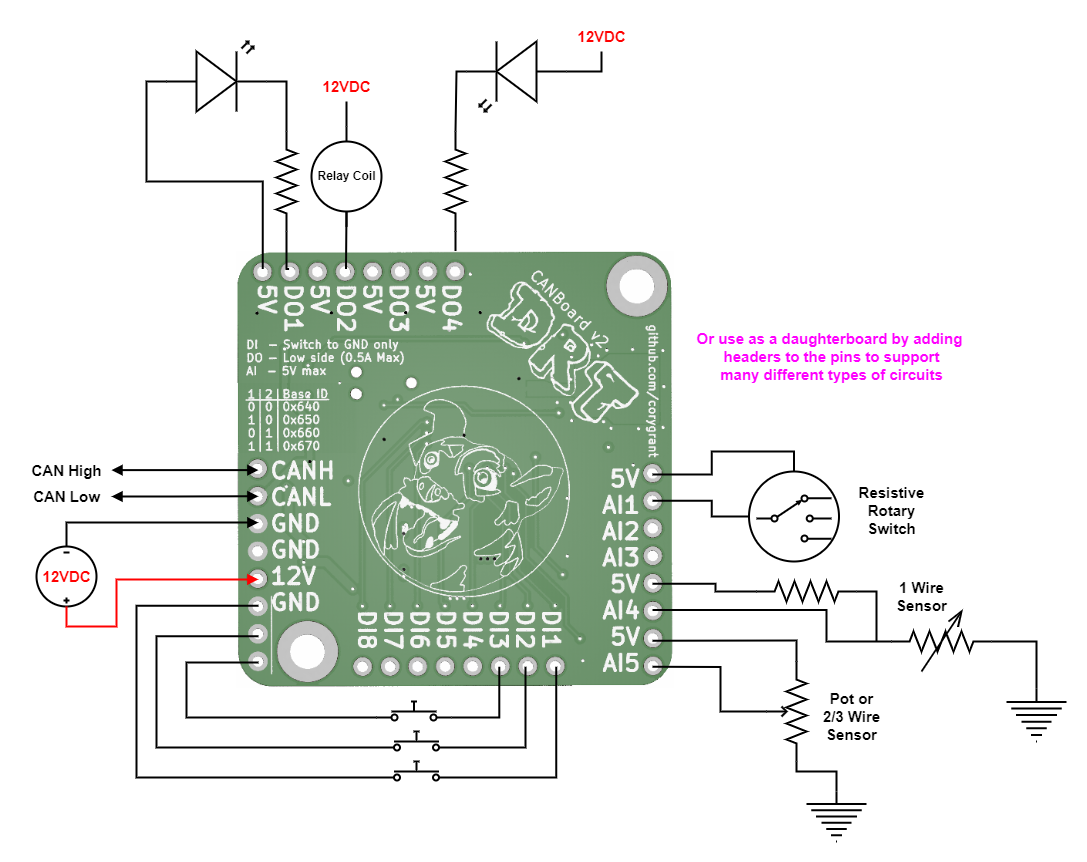
| Qty | Value | Footprint | References |
|---|---|---|---|
| 25 | 10K | Resistor_SMD:R_0805_2012Metric | R3, R10, R11, R12, R18, R19, R20, R21, R22, R24, R25, R26, R28, R29, R30, R31 +9 |
| 7 | 100nF | Capacitor_SMD:C_0805_2012Metric | C3, C4, C7, C14, C17, C18, C19 |
| 6 | 10nF | Capacitor_SMD:C_0805_2012Metric | C9, C10, C11, C12, C13, C21 |
| 5 | 4.7K | Resistor_SMD:R_0805_2012Metric | R13, R14, R15, R16, R17 |
| 4 | Conn_01x08 | Connector_PinHeader_2.54mm:PinHeader_1x08_P2.54mm_Vertical | J1, J2, J3, J4 |
| 4 | DMN2004WK | Package_TO_SOT_SMD:SOT-323_SC-70 | Q1, Q2, Q3, Q4 |
| 3 | 10uF | Capacitor_SMD:C_0805_2012Metric | C1, C2, C8 |
| 2 | 22uF | Capacitor_SMD:C_0805_2012Metric | C5, C6 |
| 2 | 27pF | Capacitor_SMD:C_0805_2012Metric | C15, C16 |
| 2 | CAN_ID | Jumper:SolderJumper-2_P1.3mm_Open_RoundedPad1.0x1.5mm | JP1, JP2 |
| 2 | MountingHole | MountingHole:MountingHole_3.2mm_M3_DIN965_Pad | H1, H2 |
| 1 | 120R | Resistor_SMD:R_0805_2012Metric | R4 |
| 1 | 120R 2W | Resistor_SMD:R_2512_6332Metric | R27 |
| 1 | 1K | Resistor_SMD:R_0805_2012Metric | R23 |
| 1 | 1uF | Capacitor_SMD:C_0805_2012Metric | C22 |
| 1 | 30R | Resistor_SMD:R_0805_2012Metric | R1 |
| 1 | 3V3TP | TestPoint:TestPoint_Pad_D1.0mm | TP1 |
| 1 | 4.7uF | Capacitor_SMD:C_0805_2012Metric | C20 |
| 1 | 5.6uH | Inductors_SMD:Wuerth_LHMI | L1 |
| 1 | 52.3K | Resistor_SMD:R_0805_2012Metric | R2 |
| 1 | 8mHz | Crystal:Crystal_SMD_5032-2Pin_5.0x3.2mm | Y1 |
| 1 | DRT_Logo | CANBoard:DingoFaceNoFill | G2 |
| 1 | DRT_Logo | CANBoard:DRTLogo | G1 |
| 1 | Ferrite_Bead_Small | Resistor_SMD:R_0805_2012Metric | FB1 |
| 1 | LD1117S33CTR | CANBoard:SOT-223 | U2 |
| 1 | LED_Small | LED_SMD:LED_0805_2012Metric | D1 |
| 1 | MCP2562 | Package_SO:SOIC-8_3.9x4.9mm_P1.27mm | U3 |
| 1 | NUP2105LT1G | CANBoard:SOT-23-3 | D2 |
| 1 | STM32F303K8T6 | Package_QFP:LQFP-32_7x7mm_P0.8mm | U4 |
| 1 | TC2030 | Connector:Tag-Connect_TC2030-IDC-NL_2x03_P1.27mm_Vertical | J5 |
| 1 | TERM_SB | Jumper:SolderJumper-2_P1.3mm_Open_RoundedPad1.0x1.5mm | JP3 |
| 1 | TPS56339DDCR | CANBoard:SOT-23-6_NoPin5 | U1 |
It measures 40 × 40 mm and has 4 copper layers, 1.6 mm thick.
83 parts, built around the STM32F303K8T6, MCP2562-H/P, LD1117S33CTR-HXY and DMN2004WK. The full list of its parts is on this page, with links to each part's symbol and footprint where PCBKit's library has them.
From the corygrant/CANBoard repository on GitHub, at the commit this page was made from: the board is CANBoard/CANBoard.kicad_pcb and its schematic CANBoard/CANBoard.kicad_sch. PCBKit opens the board in the browser, with nothing to install.
Its repository publishes it under the MIT licence: you may reuse it on that licence's terms (keep the author's notice, and for a copyleft licence share your changes alike).
jacky4566/BRZFRS_Breakout_withCAN
An inline ECU breakout board for the Subaru BRZ / Scion FR-S / Toyota 86 with a built-in CAN I/O module.


corygrant/dingoPDM
Hardware - dingoPDM is an open source, affordable automotive PDM (Power Distribution Module). Pre-assembled and tested units are available or the design can be used to build a DIY version.


can-caglar/Data-Logger-STM32
The Serial Snooper is a UART data logger with automatic baud rate detection, real-time data stamping and a command-line-interface for configuration, running on an STM32F3 microcontroller.

