Skip to the content
PCBKitNew board
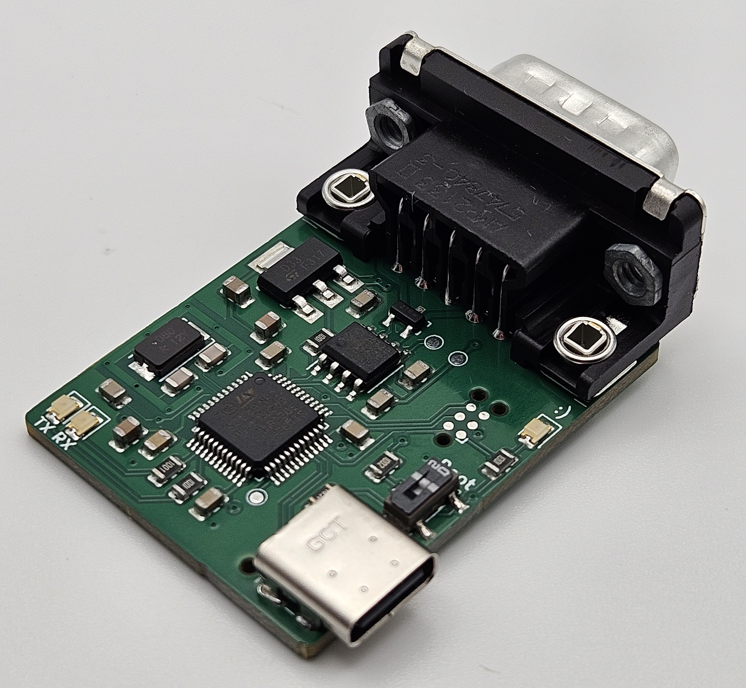
4 layers39.1 × 31 mmUSB2CAN, the printed circuit board in 3D

Hardware - USB to CAN adapter

Size
39.1 × 31 mm
Copper layers
4
Thickness
1.6 mm
Parts
37
Nets
58
Pads
159
Tracks, vias
236, 31
Pours
4
Routed
Yes
KiCad
KiCad 9.0 (file 20241229)
Created
10 Apr 2021
Updated
11 Dec 2025

Overview

USB2CAN is an open-source printed circuit board by corygrant, from the corygrant/USB2CAN_HW repository on GitHub, published under the MIT licence. It is a 4-layer board of 39.1 × 31 mm with 37 parts on 58 nets, routed with 236 tracks and 31 vias.

It is built around the LD1117S33CTR-HXY and NUP2105LT1G. Its parts include 13 capacitors, 8 resistors, 4 diodes, 3 ICs and 3 connectors. It belongs with the STM32 boards of this library.

Main components

2

README

README.md

USB2CAN_HW

USB to CAN adapter based on the work done by Hubert Denkmair and Ethan Zonca

The project was started because of the shortage of STM32 parts available.

The STM32F072xB and STM32F042x6 were both unavailable with no time frame for availability.

The STM32F302C8 was chosen primarily because it was available, and because it included CAN/USB capabilities.

The USB2CAN board does not feature galvanic isolation.

The protocol implemented is SLCAN, although not all functions are complete or included.

The firmware is a combination of canable firmware and candleLight firmware

Store

Photos

Top

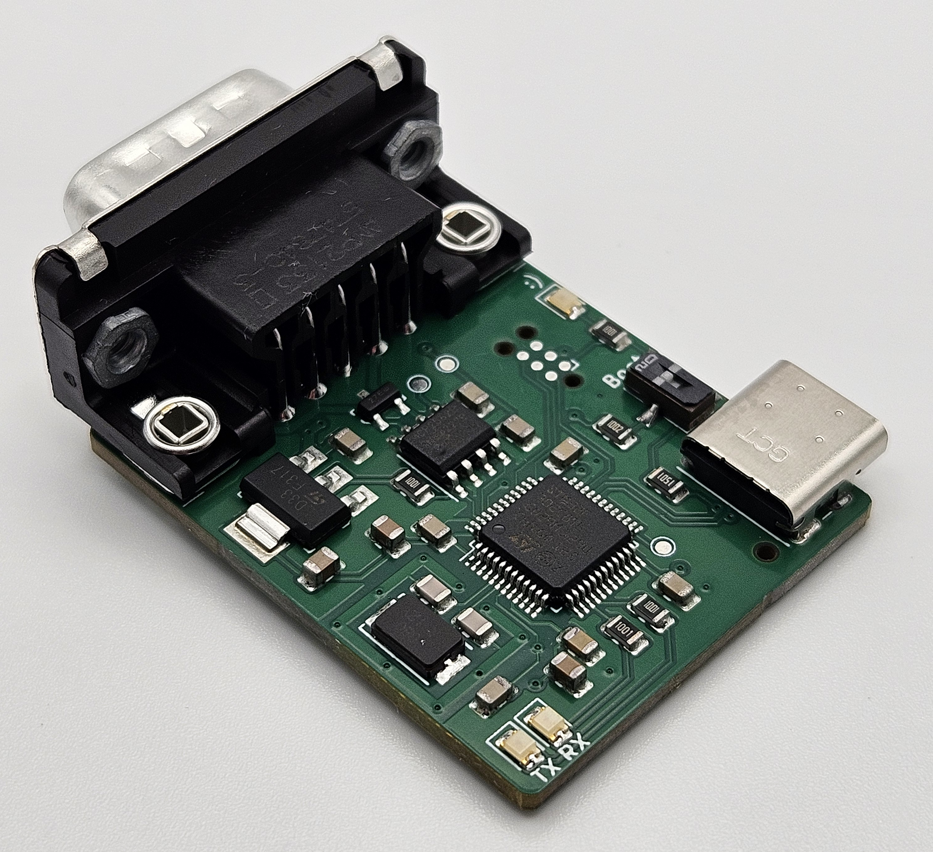
Top2

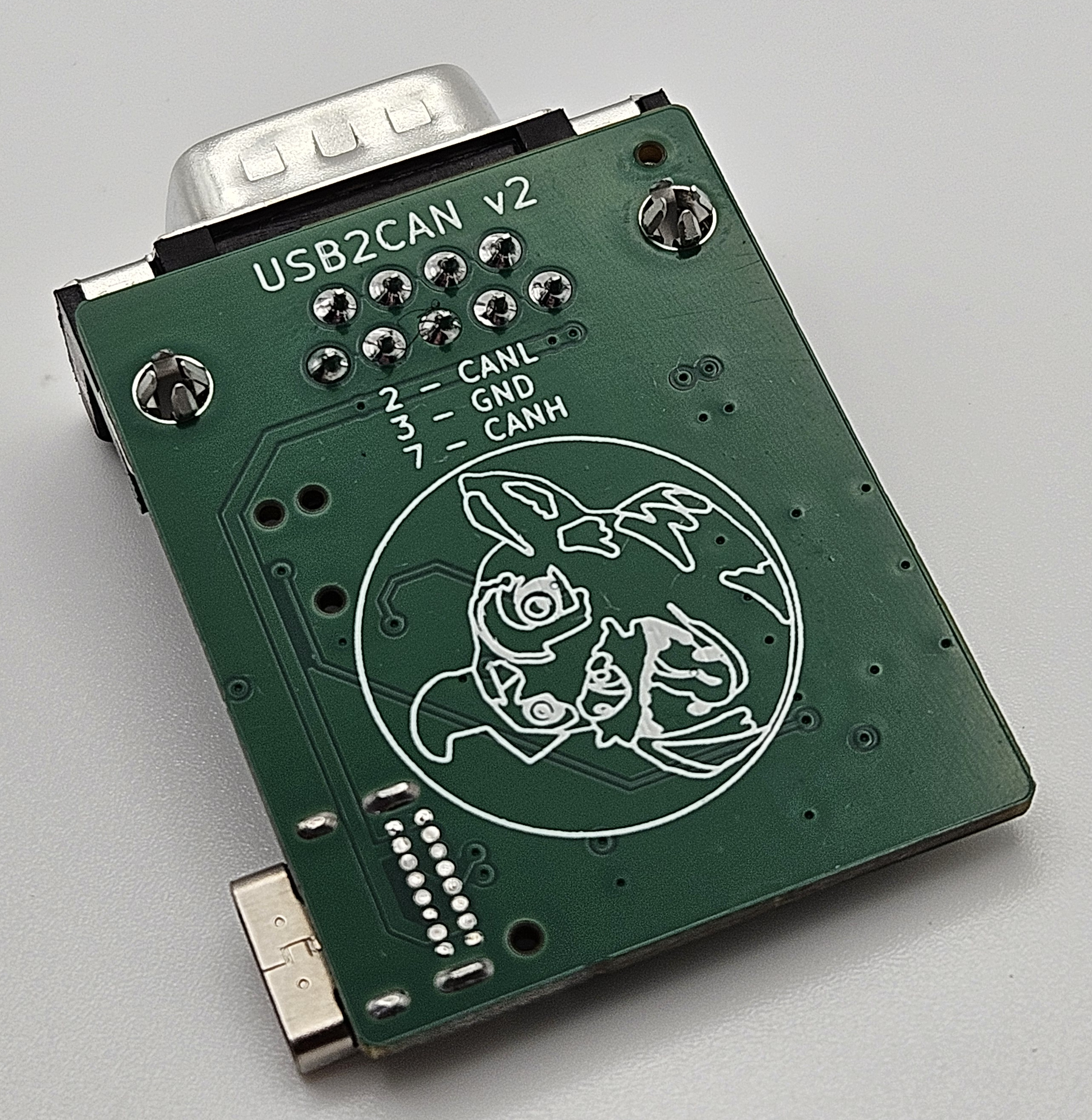
Bottom

Connection

PinFunction
1
2CAN_L
3GND
4
5
6
7CAN_H
8
9

BOM

Interactive BOM

Firmware

USB2CAN firmware

Firmware Update

Updating the USB2CAN firmware follows the same process as the dingoPDM.

See the instructions here: dingoPDM Firmware Update

Disclaimer

Please note that this product has been designed by a hobbyist, not a professional. It is intended for off-road and testing use only. Users should operate the product at their own discretion and risk. The designer explicitly disclaims any responsibility for damage or injury that may result from the use of this product.

Parts

37
QtyValueFootprintReferences
7100nFCapacitor_SMD:C_0805_2012MetricC1, C2, C3, C4, C8, C9, C10
41KResistor_SMD:R_0805_2012MetricR1, R2, R3, R8
227pFCapacitor_SMD:C_0805_2012MetricC6, C7
25.1KResistor_SMD:R_0805_2012MetricR4, R5
11.5KResistor_SMD:R_0805_2012MetricR7
110KResistor_SMD:R_0805_2012MetricR9
110nFCapacitor_SMD:C_0805_2012MetricC12
110uFCapacitor_SMD:C_0805_2012MetricC5
11uFCapacitor_SMD:C_0805_2012MetricC13
13.3V_TestPointTestPoint:TestPoint_Pad_D1.0mmTP3
14.7uFCapacitor_SMD:C_0805_2012MetricC11
15V_TestPointTestPoint:TestPoint_Pad_D1.0mmTP2
18mHzUSB2CAN:Crystal_SMD_5032-2Pin_5.0x3.2mm_HandSolderingY1
1Conn_ARM_SWD_TagConnect_TC2030-NLConnector:Tag-Connect_TC2030-IDC-NL_2x03_P1.27mm_VerticalJ4
1DB9USB2CAN:DSUB-9_Jack_5747840-3J2
1DRT_LogoUSB2CAN:DingoFaceNoFillG1
1LD1117S33CTRUSB2CAN:SOT-223U2
1LED1LED_SMD:LED_0805_2012MetricD1
1LED2LED_SMD:LED_0805_2012MetricD2
1MCP2562-E-SNPackage_SO:SOIC-8_3.9x4.9mm_P1.27mmU1
1NUP2105LT1GUSB2CAN:SOT-23-3D4
1PWRLED_SMD:LED_0805_2012MetricD3
1STM32F302C8TxPackage_QFP:LQFP-48_7x7mm_P0.5mmU3
1SW_SPDTUSB2CAN:CJS-1200TBSW1
1TestPointTestPoint:TestPoint_Pad_D1.0mmTP1
1USB_C_Receptacle_USB2.0Connector_USB:USB_C_Receptacle_GCT_USB4085J1

Questions

How big is the USB2CAN PCB?

It measures 39.1 × 31 mm and has 4 copper layers, 1.6 mm thick.

What parts does the USB2CAN use?

37 parts, built around the LD1117S33CTR-HXY and NUP2105LT1G. The full list of its parts is on this page, with links to each part's symbol and footprint where PCBKit's library has them.

Where can I download the USB2CAN KiCad files?

From the corygrant/USB2CAN_HW repository on GitHub, at the commit this page was made from: the board is USB2CAN/USB2CAN.kicad_pcb and its schematic USB2CAN/USB2CAN.kicad_sch. PCBKit opens the board in the browser, with nothing to install.

Can I use the USB2CAN design in my own project?

Its repository publishes it under the MIT licence: you may reuse it on that licence's terms (keep the author's notice, and for a copyleft licence share your changes alike).

Similar boards

  • 4 layers72.4 × 95.3 mmDingoPDM, the printed circuit board in 3D

    DingoPDM

    corygrant/dingoPDM

    Hardware - dingoPDM is an open source, affordable automotive PDM (Power Distribution Module). Pre-assembled and tested units are available or the design can be used to build a DIY version.

    156 parts128MIT
  • 4 layers40 × 40 mmCANBoard, the printed circuit board in 3D

    CANBoard

    corygrant/CANBoard

    Hardware - CAN enabled small input / output expansion board. Switch panels, steering wheel buttons/knobs, etc.

    83 parts53MIT
  • 4 layers46 × 56 mmLINBoard HW, the printed circuit board in 3D

    LINBoard HW

    corygrant/LINBoard

    73 parts1
  • 4 layers72 × 141.7 mmBRZ Breakout withCAN, the printed circuit board in 3D

    BRZ Breakout withCAN

    jacky4566/BRZFRS_Breakout_withCAN

    An inline ECU breakout board for the Subaru BRZ / Scion FR-S / Toyota 86 with a built-in CAN I/O module.

    63 partsMIT
  • 4 layers198.4 × 104.3 mmDC33, the printed circuit board in 3D

    DC33

    Maritime-Hacking-Village/Badge-2025

    Public repository for the official MHV 2025 badge.

    200 parts15CERN-OHL-W-2.0
  • 2 layers65 × 30 mmRPi pHat Thermocouple, the printed circuit board in 3D

    RPi pHat Thermocouple

    mikelawrence/RPi-pHat-Thermocouple

    Raspberry Pi Thermocouple pHat

    59 parts7MIT
  • 2 layers100 × 100 mmReflow, the printed circuit board in 3D

    Reflow

    windsorschmidt/reflow

    Hardware and firmware sources for a 2-channel reflow (toaster) oven controller. KiCad schematic & PCB.

    95 parts4MIT
  • 4 layers65 × 45 mmSTM32F446VE Module v1, the printed circuit board in 3D

    STM32F446VE Module v1

    pipipipi2002/stm32f446vetx-dev-module

    Dev Module for STM32F446VETx

    88 parts2GPL-3.0