
2 layers290.1 × 130 mm

 CoRE-MA-KING/RoboMasterHatBoard
RoboMasterHatBoard is an open-source printed circuit board by CoRE-MA-KING, from the CoRE-MA-KING/RoboMasterHatBoard repository on GitHub. It is a 2-layer board of 48.3 × 38.1 mm with 23 parts on 40 nets, routed with 79 tracks and 0 vias.
It is built around the AMS1117-3.3. Its parts include 17 connectors, 2 capacitors, 1 resistor, 1 IC and 1 diode.
ロボマス開発ボード用ハットです。
CoREに出場するロボットに利用しているメインボードとしてRoboMaster 開発ボードタイプAを利用しているので、このボードから2024年大会用に必要なピンをコネクタにまとめるための基板です。
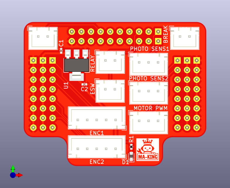
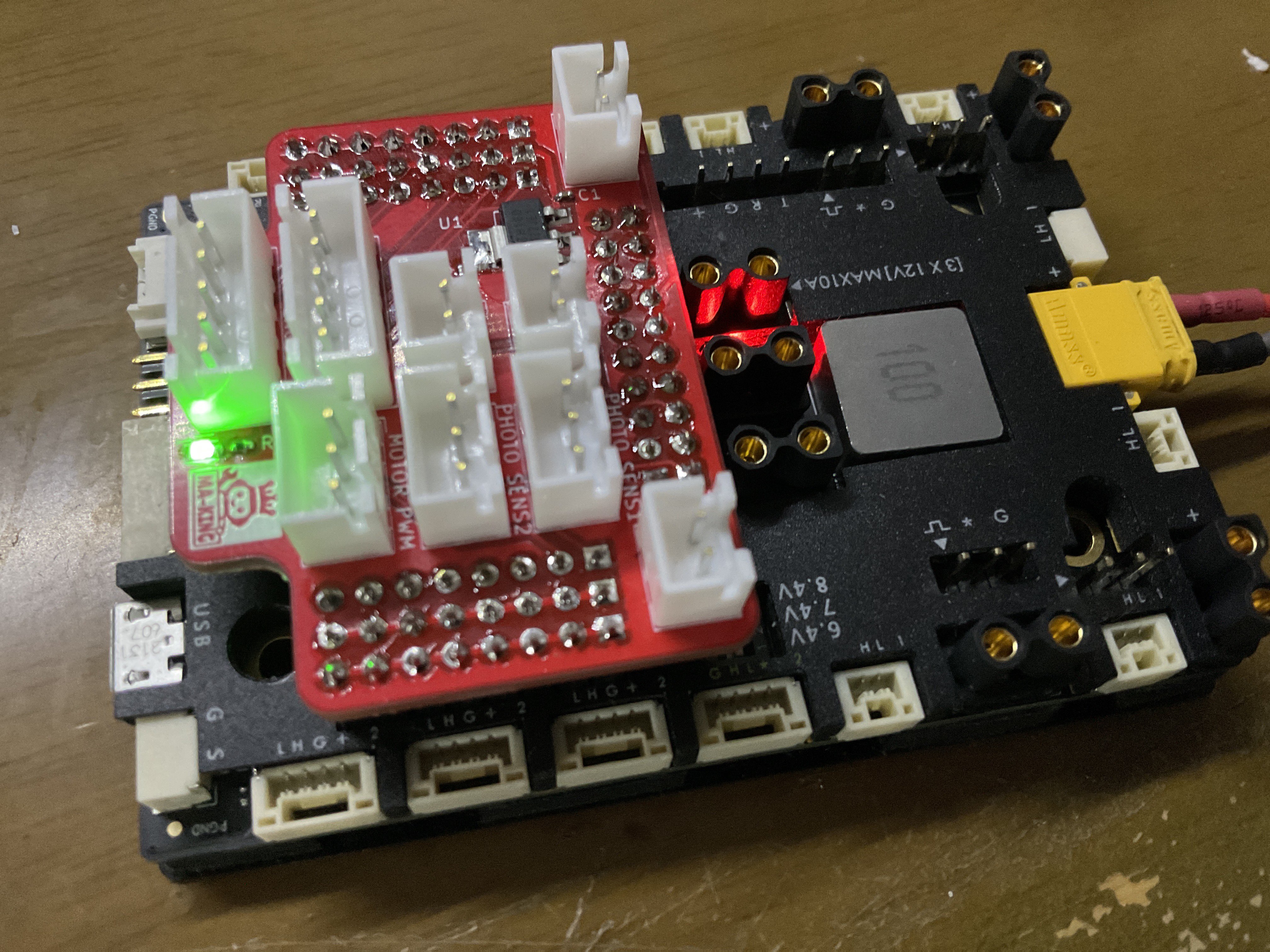
ロボマス開発ボードにはピンヘッダからいくつかのピンが出ているので、そこから今回のロボットで利用するピンを取り出します。
具体的に以下のピンを取り出します。
| ピン名 | ペリフェラル | 用途 | 備考 |
|---|---|---|---|
| PD12 | TIM4_CH1 | モータ1PWM用 | |
| PD13 | TIM4_CH2 | モータ2PWM用 | |
| PA0 | TIM2_CH1 | エンコーダ1 A相 | |
| PA1 | TIM2_CH2 | エンコーダ1 B相 | |
| PA2 | GPIO_INPUT | エンコーダ1 Z相 | |
| PI5 | TIM8_CH1 | エンコーダ2 A相 | |
| PI6 | TIM8_CH2 | エンコーダ2 B相 | |
| PI7 | GPIO_INPUT | エンコーダ2 Z相 | |
| PF0 | GPIO_INPUT | フォトインタラプタ1入力 | マイコンの内部プルアップ必須 |
| PF1 | GPIO_INPUT | フォトインタラプタ2入力 | マイコンの内部プルアップ必須 |
| PE6 | GPIO_INPUT | 非常停止ボタン入力 | マイコンの内部プルアップ必須 |
| PE12 | GPIO_OUTPUT | リレー駆動信号 | |
| PC3 | GPIO_INPUT | 撃破信号入力 | PC3は5 Vトレラントなので5 V入力可能 |
| PC1 | GPIO | 汎用GPIO | 予備ポート 5 Vトレラントピン |
v0.1の基板上のシルクと回路図上の信号線が逆になっているので注意。回路図が間違っているということにして基板のシルクか上の表に従えばOK。
基板上のコネクタのピンアサインは次の通り
| 1 | 2 | 3 |
|---|---|---|
| TIM4_CH1(PD12) | TIM4_CH2(PD13) | GND |
| 1 | 2 | 3 |
|---|---|---|
| 5 V | INPUT(PF0) | GND |
| 1 | 2 | 3 |
|---|---|---|
| 5 V | INPUT(PF1) | GND |
| 1 | 2 | 3 | 4 | 5 |
|---|---|---|---|---|
| 3.3 V | TIM2_CH1(PA1) | TIM2_CH2(PA2) | INPUT(PA2) | GND |
| 1 | 2 | 3 | 4 | 5 |
|---|---|---|---|---|
| 3.3 V | TIM8_CH1(PI5) | TIM8_CH2(Pi6) | INPUT(PI7) | GND |
| 1 | 2 |
|---|---|
| OUTPUT(PE12) | GND |
| 1 | 2 |
|---|---|
| INPUT(PE6) | GND |
| 1 | 2 |
|---|---|
| INPUT(PC3) | GND |
| 1 | 2 |
|---|---|
| INPUT(PC1) | GND |
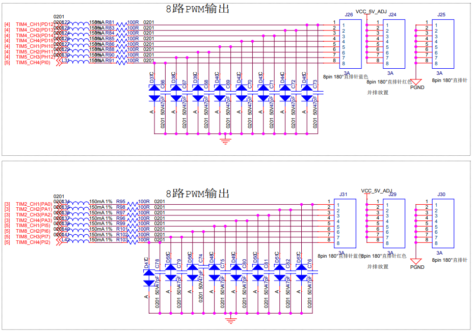
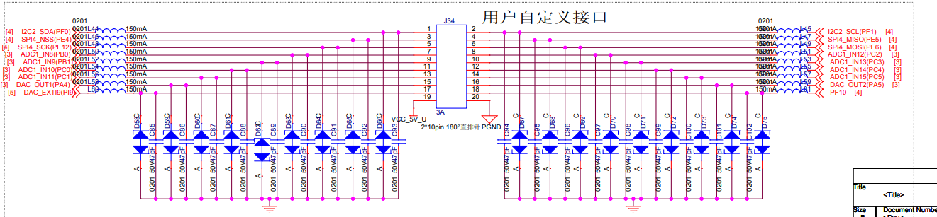
ロボマス開発ボードピンヘッダ部分のピンアサインは回路図より
| Qty | Value | Footprint | References |
|---|---|---|---|
| 6 | Conn_01x08_Socket | Connector_PinHeader_2.54mm:PinHeader_1x08_P2.54mm_Vertical | J1, J2, J3, J4, J5, J6 |
| 4 | Conn_01x02_Pin | Connector_JST:JST_XH_B2B-XH-A_1x02_P2.50mm_Vertical | J9, J10, J16, J17 |
| 3 | Conn_01x03_Pin | Connector_JST:JST_XH_B3B-XH-A_1x03_P2.50mm_Vertical | J11, J14, J15 |
| 2 | C | Capacitor_SMD:C_0402_1005Metric | C1, C2 |
| 2 | Conn_01x05_Pin | Connector_JST:JST_XH_B5B-XH-A_1x05_P2.50mm_Vertical | J12, J13 |
| 2 | Conn_01x10_Socket | Connector_PinHeader_2.54mm:PinHeader_1x10_P2.54mm_Vertical | J7, J8 |
| 1 | AMS1117-3.3 | Package_TO_SOT_SMD:SOT-223-3_TabPin2 | U1 |
| 1 | LED | Diode_SMD:D_0603_1608Metric | D1 |
| 1 | LOGO | LOGO | |
| 1 | R | Resistor_SMD:R_0402_1005Metric | R1 |

pascallanger/DIY-Multiprotocol-TX-Module
Multiprotocol TX Module (or MULTI-Module) is a 2.4GHz transmitter module which controls many different receivers and models.

fossasia/pslab-hardware
PSLab Hardware Design and Schematics https://pslab.io


MaltWhiskey/Mega-Cube
16x16x16 PL9823 Cube with Teensy 4.0 and FlexIO driver


shamansystems/Cheap-FOCer-2
Low-Cost Motor Controller based on the VESC 6
It measures 48.3 × 38.1 mm and has 2 copper layers, 1.6 mm thick.
23 parts, built around the AMS1117-3.3. The full list of its parts is on this page, with links to each part's symbol and footprint where PCBKit's library has them.
From the CoRE-MA-KING/RoboMasterHatBoard repository on GitHub, at the commit this page was made from: the board is RoboMasterHatBoard.kicad_pcb and its schematic RoboMasterHatBoard.kicad_sch. PCBKit opens the board in the browser, with nothing to install.
Its repository states no licence, so its author keeps all rights: ask CoRE-MA-KING before reusing the design.