4 layers100 × 100 mm

 conifarad/open-lightning-trigger
A low-cost optical camera trigger for lightning and other phenomena
Open lightning trigger is an open-source printed circuit board by conifarad, from the conifarad/open-lightning-trigger repository on GitHub, published under the CERN-OHL-P-2.0 licence. It is a 2-layer board of 70 × 55 mm with 50 parts on 39 nets, routed with 239 tracks and 17 vias.
It is built around the ATTINY84A-SSF, LTV-827S and SJ1-2503A. Its parts include 19 resistors, 10 diodes, 7 capacitors, 3 ICs and 3 switches. It belongs with the AVR (ATmega, ATtiny) boards of this library.


A low-cost optical camera trigger for lightning and other phenomena, based on the ATTiny84A microcontroller.
⚠️ This is a beta version. It has only been minimally tested to confirm basic functionality. Build at your own risk!
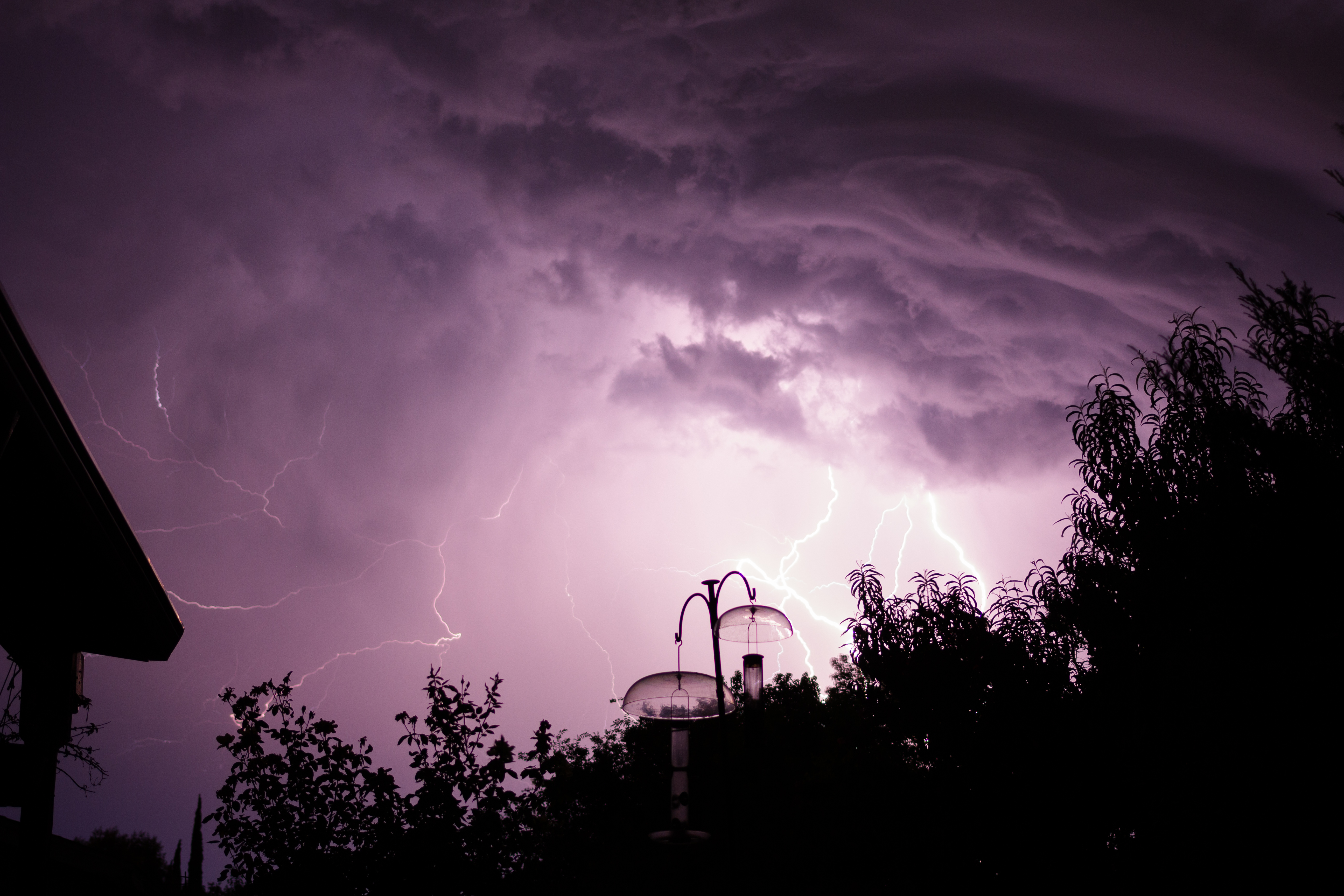
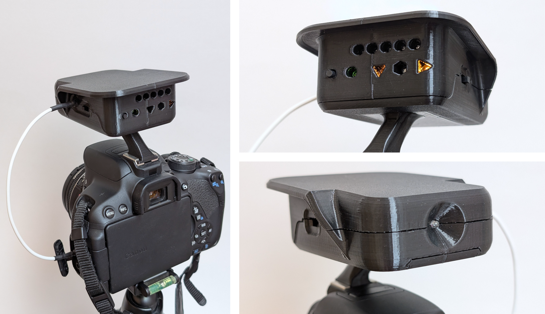
I wanted a way to trigger my Canon DSLR on lightning, fireworks, and other optical flashes; however, current trigger systems cost hundreds of dollars. The goal of this project is to create a low-cost trigger system that can be assembled by anyone with minimal SMD soldering experience (such as myself) and access to a 3D printer and an Arduino for programming.
I have only tested the trigger with the Canon EOS T5i. However, by using a different wire to connect the camera and trigger, it should be adaptable to numerous camera models. See the Assembly doc for details.
See docs/assembly.md for information on assembly, programming, etc.
The trigger takes 2x AAA batteries; either alkaline or NiMH (rechargeable) works.
Attach the trigger to the hotshoe mount of your camera and connect the output jack to the wired remote input of your camera using an appropriate cable.
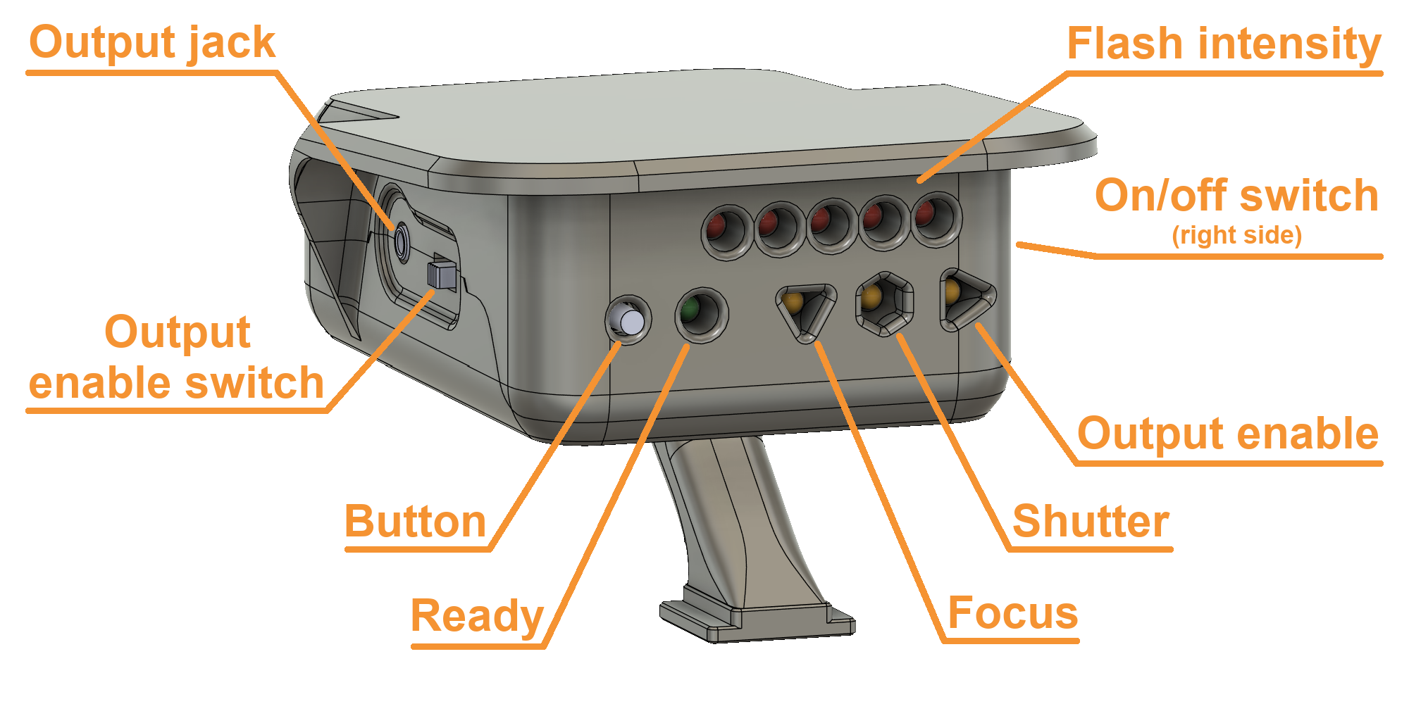
The trigger is operated as follows:
See this video for a demo of the trigger on nearby fireworks.
The most difficult design decision of this project was determining the necessary bandwidth of the amplifier stages. To estimate an acceptable bandwidth, I used data scraped from graphs of lightning illuminance over time by Quick and Krider (2013) and simulated different filtering schemes on these waveforms. The current amplifier bandwidth of approximately 110-4400 Hz was chosen to preserve peak heights above an arbitrary threshold while hopefully eliminating the effects of most natural lighting variations (~1 Hz). Unfortunately, artificial light sources exhibiting even slight mains-frequency oscillations are still able to interfere with the sensor.
A KiCad project with simple AC/transient simulations of the amplifier is found in the simulation folder.
Should there be a version 2 of this project, I hope to integrate many changes:
Files in the enclosure, hardware, and simulation folders are licensed under CERN-OHL-P v2.
See LICENSE-CERN-OHL-P for details.
The above readme as well as files in the docs folder are licensed under CC BY-SA 4.0.
All other files are under the MIT license. See LICENSE-MIT for details.
| Qty | Value | Footprint | References |
|---|---|---|---|
| 11 | 1.5k | Resistor_SMD:R_0805_2012Metric_Pad1.20x1.40mm_HandSolder | R1, R2, R3, R4, R5, R6, R7, R8, R9, R10, R11 |
| 5 | LED_RED | conifarad:LED_D3.0mm_Horizontal_O6.35mm_Z2.0mm_NoSilk | D2, D3, D4, D5, D6 |
| 4 | 470 | Resistor_SMD:R_0805_2012Metric_Pad1.20x1.40mm_HandSolder | R12, R14, R18, R19 |
| 3 | 4.7u | Capacitor_SMD:C_0805_2012Metric_Pad1.18x1.45mm_HandSolder | C1, C3, C5 |
| 3 | LED_AMBER | conifarad:LED_D3.0mm_Horizontal_O6.35mm_Z2.0mm_NoSilk | D7, D8, D9 |
| 2 | 18k | Resistor_SMD:R_0805_2012Metric_Pad1.20x1.40mm_HandSolder | R13, R15 |
| 2 | 1n | Capacitor_SMD:C_0805_2012Metric_Pad1.18x1.45mm_HandSolder | C2, C4 |
| 2 | 1u | Capacitor_SMD:C_0805_2012Metric_Pad1.18x1.45mm_HandSolder | C6, C7 |
| 2 | 470k | Resistor_SMD:R_0805_2012Metric_Pad1.20x1.40mm_HandSolder | R16, R17 |
| 2 | SW_SPDT | conifarad:SW_SLW-1298856-5A-RA-N-D_custom | SW1, SW3 |
| 1 | ATtiny84A-SS | Package_SO:SOIC-14_3.9x8.7mm_P1.27mm | U2 |
| 1 | AVR-ISP-6 | Connector_PinHeader_2.54mm:PinHeader_2x03_P2.54mm_Vertical | J2 |
| 1 | Battery | conifarad:BatteryHolder_Keystone_2468_2xAAA | BT1 |
| 1 | D_Photo | conifarad:LED_D3.0mm_Horizontal_O6.35mm_Z2.0mm_NoSilk | D10 |
| 1 | LED_GREEN | conifarad:LED_D3.0mm_Horizontal_O6.35mm_Z2.0mm_NoSilk | D1 |
| 1 | LTV-827S | Package_DIP:SMDIP-8_W9.53mm | U3 |
| 1 | Opamp_Dual | Package_SO:SOIC-8_3.9x4.9mm_P1.27mm | U1 |
| 1 | SJ1-2503A | conifarad:SAMESKY_SJ1-2503A | J1 |
| 1 | SW_Push | conifarad:SW_TS11-674-153-BK-160-RA-D | SW2 |
| 1 | TP_GND | TestPoint:TestPoint_THTPad_D2.0mm_Drill1.0mm | TP5 |
| 1 | TP_PD | TestPoint:TestPoint_THTPad_D2.0mm_Drill1.0mm | TP1 |
| 1 | TP_REF | TestPoint:TestPoint_THTPad_D2.0mm_Drill1.0mm | TP4 |
| 1 | TP_ST1 | TestPoint:TestPoint_THTPad_D2.0mm_Drill1.0mm | TP2 |
| 1 | TP_ST2 | TestPoint:TestPoint_THTPad_D2.0mm_Drill1.0mm | TP3 |

ArgonautGit/kicad-projects
Just some Kicad projects I've worked on over the years. Most are unfinished or don't work well.

sensslen/Cfg.CameraControl.Hardware
Hardware needed to control a lanc camera with a PTZ head


petrmikheev/endeavour
Endeavour - open-source FPGA board and SoC ==========================================


It measures 70 × 55 mm and has 2 copper layers, 1.6 mm thick.
50 parts, built around the ATTINY84A-SSF, LTV-827S and SJ1-2503A. The full list of its parts is on this page, with links to each part's symbol and footprint where PCBKit's library has them.
From the conifarad/open-lightning-trigger repository on GitHub, at the commit this page was made from: the board is hardware/open_lightning_trigger/open_lightning_trigger.kicad_pcb and its schematic hardware/open_lightning_trigger/open_lightning_trigger.kicad_sch. PCBKit opens the board in the browser, with nothing to install.
Its repository publishes it under the CERN-OHL-P-2.0 licence: you may reuse it on that licence's terms (keep the author's notice, and for a copyleft licence share your changes alike).