
6 layers90 × 153 mm
Blackpants
o7-machinehum/Blackpants
Open blackpants.kicadpro for the active A523 schematic and PCB. It replaces the A33 hierarchy and uses AXP717C + AXP323 with 2GB LPDDR4.
300 parts189MIT

 con-f-use/Wiilaserbar1
A driver board, case and holder for infrared lasers meant to replace the sensor bar of a Nintendo Wii.
Wiilaserbar is an open-source printed circuit board by con-f-use, from the con-f-use/Wiilaserbar repository on GitHub. It is a 2-layer board of 20.7 × 20.4 mm with 24 parts on 13 nets, routed with 82 tracks and 4 vias.
It is built around the AOZ1280CI. Its parts include 5 connectors, 3 capacitors, 3 resistors, 3 diodes and 2 ICs. It belongs with the sensors and measurement and retro computing and games boards of this library.
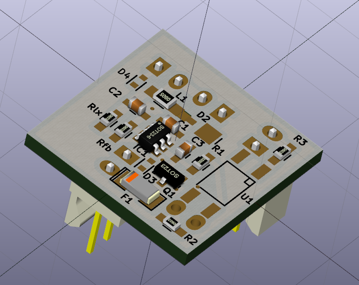
A driver board, case and holder for infrared lasers meant to replace the sensor bar of a Nintendo Wii.
Be VERY CAREFUL in selecting the output power. Infrared lasers cannot be seen by the naked eye no matter the power. They can permanently damage your eyes even at less then 1mW!!! You might blind yourself in an instant!
This is a replacement for the Wii sensor bar. The populatd board powers two infrared laser diode modules. These in turn project infrared dots on a surface that the Wiimotes can pick up on just as they were standard infrared diodes of the "sensor" bar. You can buy infrared laser diode modules on eBay or Aliexpress cheaply. I used cheap 890nm modules from China said to emit 30mW (the output power with mine was exaggerated - actually measured power at a university lab was ~2mW).
The driver board was done in KiCAD while the case was 3D modelled in FreeCAD and printed on a LulzBot Mini.
| Qty | Value | Footprint | References |
|---|---|---|---|
| 3 | 1k5 | Resistors_SMD:R_0603_HandSoldering | R1, R2, R3 |
| 2 | TVS | Diodes_SMD:SOD-523 | D3, D4 |
| 1 | 10n | Capacitors_SMD:C_0603_HandSoldering | C1 |
| 1 | 10u | Capacitors_SMD:C_0603_HandSoldering | C2 |
| 1 | 15k | Resistors_SMD:R_0603_HandSoldering | Rfb |
| 1 | 250mA | SMD_Packages:SMD-1206_Pol | F1 |
| 1 | 2u2 | Resistors_SMD:R_0805_HandSoldering | L1 |
| 1 | 4u7 | Capacitors_SMD:C_0603_HandSoldering | C3 |
| 1 | 82k | Resistors_SMD:R_0603_HandSoldering | Rlx |
| 1 | AOZ1280 | Housings_SOT-23_SOT-143_TSOT-6:SOT-23-6 | IC1 |
| 1 | D_Schottky_Small | jcgb:DIODE_POWERMITE | D2 |
| 1 | Gnu_GPL | jcgb:gnu_gpl | LO1 |
| 1 | LTV-354T-6pin | Opto-Devices:Optocoupler_SMD_HandSoldering_KPC357_LTV35x_PC357_SingleChannel | U1 |
| 1 | PMOS | Housings_SOT-23_SOT-143_TSOT-6:SOT-23 | Q1 |
| 1 | Vin | w_conn_kk100:kk100_22-23-2021 | J1 |
| 1 | lsr1 | w_conn_kk100:kk100_22-23-2021 | J4 |
| 1 | lsr2 | w_conn_kk100:kk100_22-23-2021 | J3 |
| 1 | open hardware | w_logo:Logo_silk_OSHW_6x6mm | LOGO1 |
| 1 | stay on | jcgb:PINHEAD1-2 | J5 |
| 1 | unethische.org | jcgb:unethi_silk | O1 |
| 1 | wii | w_conn_kk100:kk100_22-23-2021 | J2 |
o7-machinehum/Blackpants
Open blackpants.kicadpro for the active A523 schematic and PCB. It replaces the A33 hierarchy and uses AXP717C + AXP323 with 2GB LPDDR4.


It measures 20.7 × 20.4 mm and has 2 copper layers, 1.6 mm thick.
24 parts, built around the AOZ1280CI. The full list of its parts is on this page, with links to each part's symbol and footprint where PCBKit's library has them.
From the con-f-use/Wiilaserbar repository on GitHub, at the commit this page was made from: the board is board/wiilaserbar.kicad_pcb. PCBKit opens the board in the browser, with nothing to install.
Its repository states no licence, so its author keeps all rights: ask con-f-use before reusing the design.