Skip to the content
PCBKitNew board
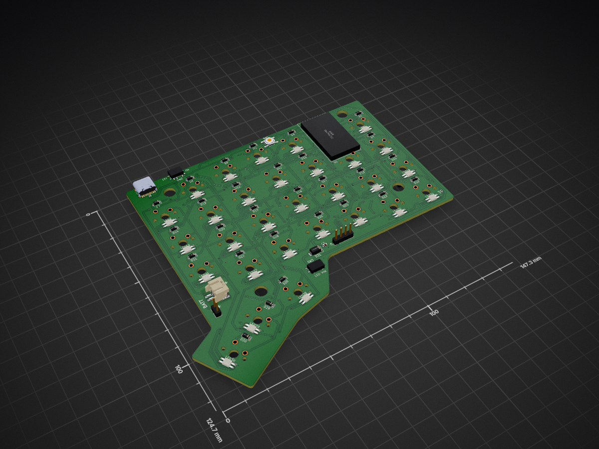
2 layers147.3 × 124.7 mmLeft, the printed circuit board in 3D

60 key split keyboard

Size
147.3 × 124.7 mm
Copper layers
2
Thickness
1.6 mm
Parts
101
Nets
90
Pads
414
Tracks, vias
1,406, 341
Pours
1
Routed
Yes
KiCad
KiCad 9.0 (file 20241229)
Created
7 Apr 2026
Updated
5 Jul 2026

Overview

Left is an open-source printed circuit board by codefresco, from the codefresco/Wings60 repository on GitHub, published under the GPL-3.0 licence. It is a 2-layer board of 147.3 × 124.7 mm with 101 parts on 90 nets, routed with 1,406 tracks and 341 vias.

It is built around the 1N4148W. Its parts include 61 diodes, 4 connectors, 3 switches, 1 capacitor and 1 resistor. It belongs with the keyboards and input boards and the AVR (ATmega, ATtiny) boards of this library.

Main components

1

README

readme.md

Wings60

Wings60 is an open source split keyboard designed after trying many existing split layouts.

Why this layout

This keyboard is different in:

  • Improved key access for the thumb cluster, two 1.5u key with good access.
  • Uses a natural thumb cluster orientation selected after testing many existing layouts.
  • Uses the most popular column stagger.
  • Keeps the same PCB usable for wired or wireless builds, including a power slide switch, JST PH2.0 battery plug, and between-halves interconnects on the PCB.
  • Uses USB-C for wired interconnect between halves, it can be hot-plugged without damaging microcontrollers.
  • Supports pro-micro pinout controllers such as Nice!Nano, Pro Micro ATmega32u4, and Pro Micro RP2040.
  • Uses low-power RGB LEDs (SK6803 mini-e), which draw less power than common WS2812B and SK6812 variants.
  • Includes a slide switch to cut LED power for zero LED idle current in power-conscious assemblies.
  • Stays compact while keeping a top number row.

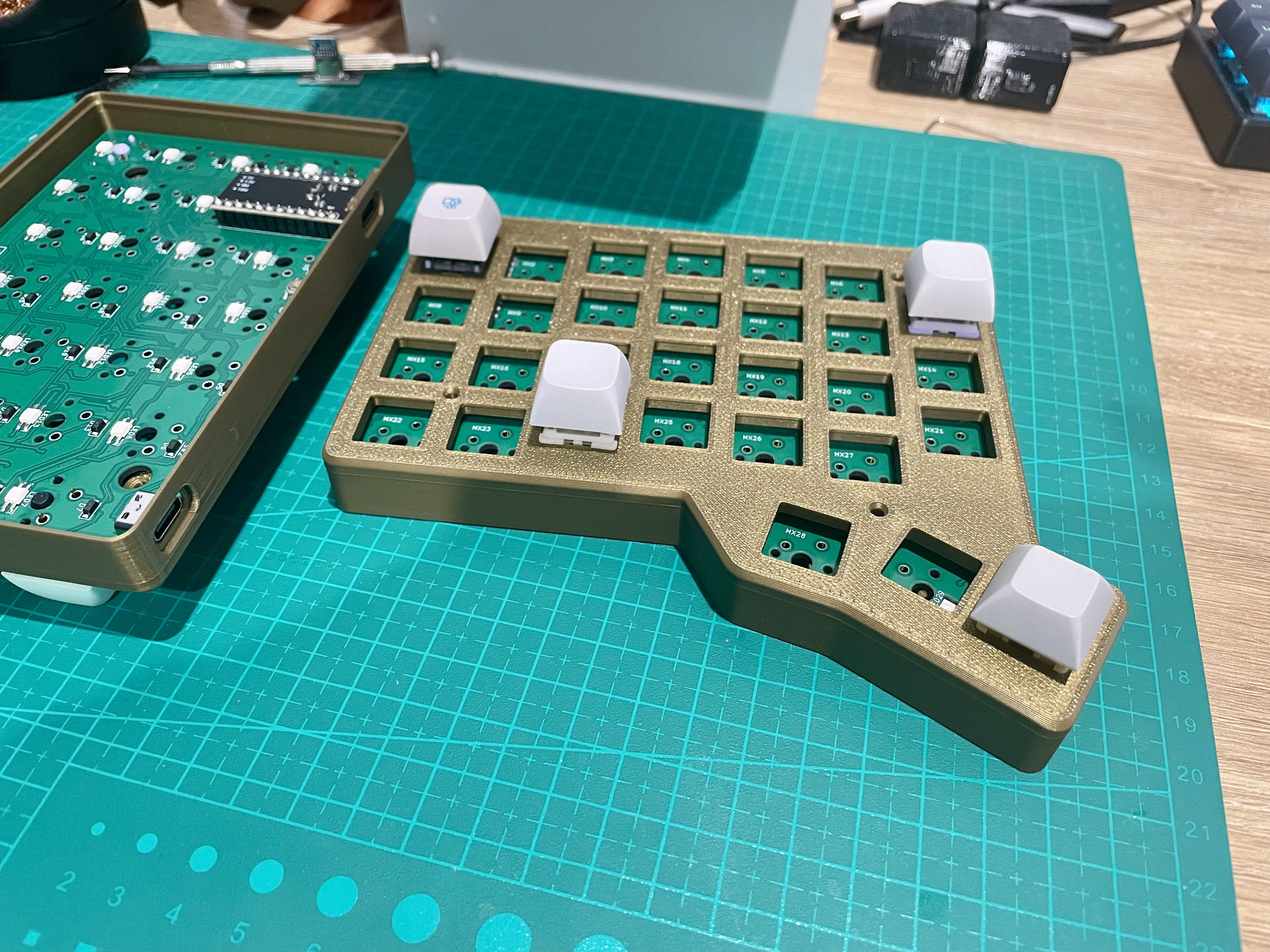
Wings60 case view

How to assemble

[!WARNING] If you use a 3V microcontroller (for example Nice!Nano or RP2040), do not plug a powered USB cable into the between-halves interconnect USB-C port. With a standard usb c cable and device, this would not be an issue bacause the CC pin on the interconnect is not connected. With a floating CC pin the device would not power the USB-C port. However, some USB-A to USB-C cables or devices do not comply with this standard and present 5v to the USB-C VBUS anyway, and this can damage the microcontroller. To make it mistake proof:

  • For nice! nano compatible and wireless builds print the case with interconect port covered
  • For wired builds with 3V microcontrollers do not connect he VCC pin on microcontroller to the pcb (don't pin if using mill max or similar pins, clip the pin if using ez solder, etc.) and bridge the VCC pin of the PCB to RAW using a short wire on back of the PCB

[!WARNING] Before soldering switches, make sure the microcontroller USB connector is clearly accessible in your chosen case. After switches are soldered, the case top is sandwiched between switches and PCB, and changing the top case becomes difficult. If you want to be able to remove the PCB more easily, check the PCB-mount-switches case variant in case.

Bill of materials

  • See designs in case, pick one and print it. You can also design your own case around the Case design outline, both dxf and svg are included.
  • Sockets for MCU: one of EZ-Solder Machine Sockets or a 40-pin machined IC breakable female header strip with Mill-Max pins is recommended for a total socket height of 4.5-5mm. This works best with the 3D printable case designs in case. Check USB connector height after assembly against the case USB opening. If your USB sits higher/lower, use the adjustable USB case variant described in case/readme.md. A good guide to socketing microcontrollers is available here: Machine pin socket guide
  • Two pro micros: use any board with firmware already available in firmware, or any pro-micro-pinout compatible board and adjust firmware as needed. For wireless, use Nice!Nano or compatible SuperMini nRF52840.
  • Either 4x 9-10mm standoffs with 4x M2x8 and 4x M2x4 screws for each half, or 4x M2x4 heat inserts with the heat-insert-compatible case bottom. See case/readme.md.
  • Non-slip rubber feet, 4x per half. 6mm diameter x 2mm height works well.
  • [Wired only] A USB-C to USB-C cable for connecting the right and left halves.
  • [Wireless only] A JST PH2.0 battery up to 5mm height. Check dimensions against the case if using the designs in case.
  • Switches and keycaps.

Wired build

  1. Flash firmware using instructions here firmware/readme.md
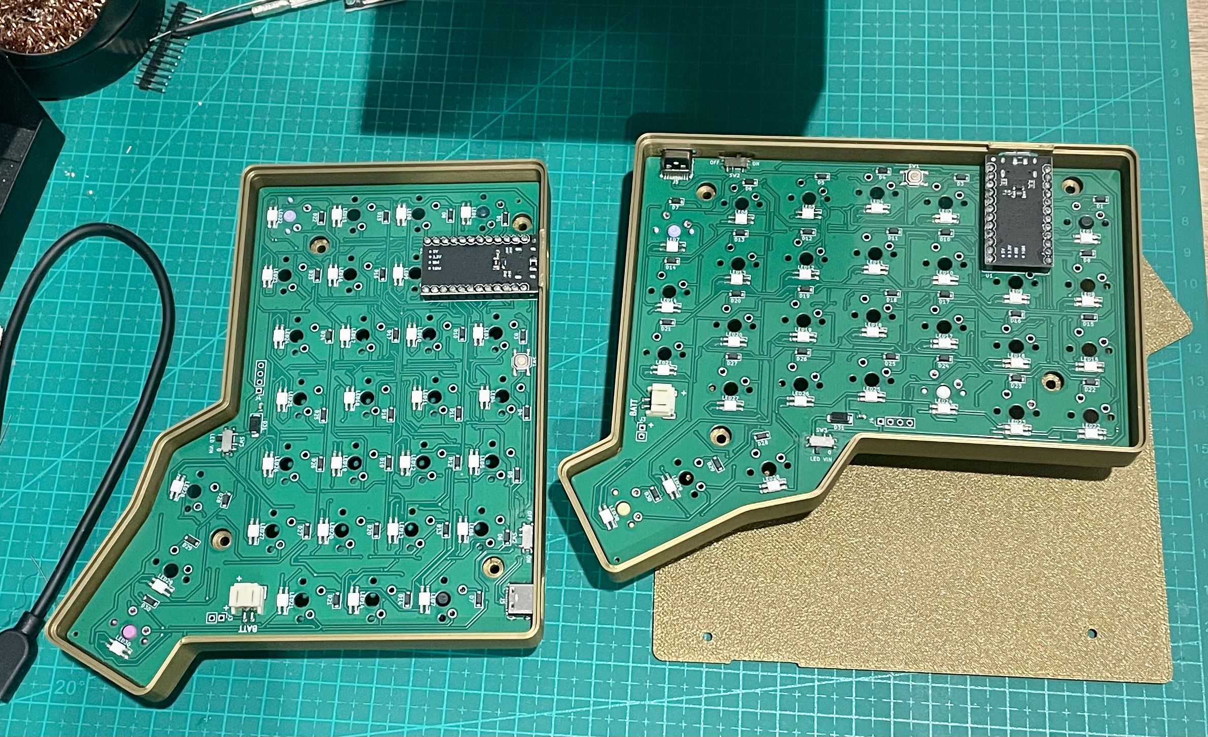
  2. Solder and socket the microcontrollers to PCBs, face down. USB side must face the PCB. A good socketing guide: Splitkb microcontroller guide
  3. Check USB height to make sure it fits the case designs in case. If it fits fixed-USB, use that variant; otherwise adjust USB height in the movable/adjustable variant in your slicer.
  4. Fit switches to the case, minding pin orientation.

Assembly orientation

  1. Fit the PCB to the case with flat side toward switches and components facing away from switches, so switch pins come out through the PCB. PCB should rest on the bottom of the switches. You may need gentle pressure for switch mounting pins to pop in.
  2. Check no switch has popped out, and all switches are firmly seated on top of the case top side. Then solder all switch legs to the PCB.
  3. If using standoff bottoms, screw each standoff to the case with M2x8 screws. V-shaped heads sit flush in the top-side recesses.
  4. Screw case bottoms to standoffs using M2x4 screws, then apply non-slip feet.
  5. If using heat-insert bottoms, install heat inserts and fit the bottom to the top using M4x8 screws.

The halves can now be connected using the USB-C cable. Connect one microcontroller to your PC (either half, but not both).

Use Vial to configure the keyboard. Configuration is saved to the half connected to the PC.

Wireless build

TBD

Parts

101
QtyValueFootprintReferences
301N4148WLibrary:D_SOD-123D1, D2, D10, D11, D12, D13, D14, D15, D16, D17, D18, D19, D20, D21, D22, D23 +14
30SK6803 MINI-ELibrary:SK6803_MINI-E_v3.5.5_1LED1, LED2, LED10, LED11, LED12, LED13, LED14, LED15, LED16, LED17, LED18, LED19, LED20, LED21, LED22, LED23 +14
28MX_SW_solderLibrary:SW_MX_1uMX1, MX2, MX10, MX11, MX12, MX13, MX14, MX15, MX16, MX17, MX18, MX19, MX20, MX21, MX22, MX23 +12
2MX_SW_solderLibrary:SW_MX_1.5uMX29, MX30
2SW_SPDTLibrary:SW_SPDT_Shouhan_MSK12C02SW2, SW3
11N4001Library:D_SMAD31
14.7uFLibrary:C_0603_1608MetricC1
1500Library:R_0402_1005MetricR2
1Conn_01x02Library:JST S2B-PH-SM4-TB-1x02-JST-PHJ1
1Conn_01x02_PinLibrary:PinHeader_1x02_P2.54mm_VerticalJ3
1Conn_01x04_PinLibrary:PinHeader_1x04_P2.54mm_VerticalJ4
1ProMicroLibrary:ProMicro_USBdnU1
1SW_PushLibrary:SW_SPST_TL3342SW1
1USB_C_Receptacle_USB2.0_14PLibrary:USB_C_Receptacle_HRO_TYPE-C-31-M-12J5

Questions

How big is the Left PCB?

It measures 147.3 × 124.7 mm and has 2 copper layers, 1.6 mm thick.

What parts does the Left use?

101 parts, built around the 1N4148W. The full list of its parts is on this page, with links to each part's symbol and footprint where PCBKit's library has them.

Where can I download the Left KiCad files?

From the codefresco/Wings60 repository on GitHub, at the commit this page was made from: the board is production/kicad/left/left.kicad_pcb and its schematic production/kicad/left/left.kicad_sch. PCBKit opens the board in the browser, with nothing to install.

Can I use the Left design in my own project?

Its repository publishes it under the GPL-3.0 licence: you may reuse it on that licence's terms (keep the author's notice, and for a copyleft licence share your changes alike).

Similar boards

  • 4 layers99 × 53.3 mmPSLab, the printed circuit board in 3D

    PSLab

    fossasia/pslab-hardware

    PSLab Hardware Design and Schematics https://pslab.io

    199 parts1.7kApache-2.0
  • 2 layers208.8 × 396.9 mmFerris, the printed circuit board in 3D

    Ferris

    pierrechevalier83/ferris

    A low profile split keyboard designed to satisfy one single use case elegantly

    145 parts1.3k
  • 2 layers285.5 × 95 mmReviung46 ver1 1, the printed circuit board in 3D

    Reviung46 ver1 1

    gtips/reviung

    The REVIUNG41 is 41-key column staggered keyboard.

    119 parts517MIT
  • 4 layers95.6 × 73.6 mmMathpad, the printed circuit board in 3D

    Mathpad

    Summa-Cogni/Mathpad

    A mathematical keypad for students and professionals

    93 parts243
  • 2 layers141.5 × 83 mmRolio, the printed circuit board in 3D

    Rolio

    MickiusMousius/Rolio46Keyboard

    A split wireless keyboard based on the Corne and Sofle

    110 parts236MIT
  • 6 layers160 × 100 mmAdrmu6layer, the printed circuit board in 3D

    Adrmu6layer

    marcoreps/ADRmu

    ADR1000 10V standard

    240 parts149
  • 2 layers99.1 × 90.7 mmBgkeeb, the printed circuit board in 3D

    Bgkeeb

    sadekbaroudi/bgkeeb

    This is a reversible 100mm x 100mm pcb with support for mx or choc switches (no hotswap), per key led, rotary encoders, and exposes the SDA/SCL/GND/VCC lines in the form of the pimoroni trackball pins (meaning you can…

    108 parts108
  • 2 layers229.8 × 102.6 mmBw2, the printed circuit board in 3D

    Bw2

    hazels-garage/bad-wings

    Bad Wings

    107 parts107CC-BY-SA-4.0