
2 layers78 × 130 mm
Lofence
kiu/lofence
LoFence is a LoRaWAN capable IoT electric fence monitoring system running on the The Things Network.
65 parts142MIT
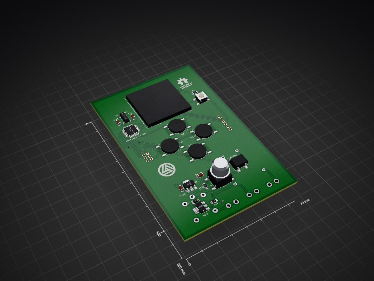
 Clewsy/grinder_timer1
A programmable timer for a coffee grinder. Mirrored from GitLab.
Grinder timer is an open-source printed circuit board by Clewsy, from the Clewsy/grinder_timer repository on GitHub, published under the MIT licence. It is a 2-layer board of 75 × 120 mm with 35 parts on 42 nets, routed with 215 tracks and 25 vias.
It is built around the ATMEGA328PB-AU. Its parts include 7 switches, 6 capacitors, 5 resistors, 5 connectors and 2 ICs. It belongs with the AVR (ATmega, ATtiny) boards of this library.
Modelled and printed a bezel for the OLED to tidy-up the enclosure. Modelled in freecad, printed on a Prusa CORE One+. CAD files and photo here.
More information can be found at my project page.
Improvements since rev1:
Repo contents:
Note: I used an ATmega328PB which isn't supported by the latest avr-libc package. For the code in this repo to compile, using the included makefile, options are: a) Modify to use an ATmega328; or b) Manually install the libatmega328pb.a, iom328pb.h and crtatmega328pb.o files; or c) Use platformio instead of the makefile.

This is a programmable timer tethered to a Rancilio Rocky coffee grinder. The Rocky is a "dumb" grinder and electrically very simple. Basically it's an ac motor with an on/off switch and a momentary push-button to grind. This project adds an electronic timer so that repeatable grind quantities can be produced without having to stand over the grinder. Features:
The code, schematic and PCB layout are all included here on gitlab. More information can be found at my project page.
Proudly mentioned at hackaday.com.

| Qty | Value | Footprint | References |
|---|---|---|---|
| 2 | 0.1uF | Capacitor_SMD:C_1206_3216Metric_Pad1.42x1.75mm_HandSolder | C2, C3 |
| 2 | 1.8k | Resistor_SMD:R_1206_3216Metric_Pad1.42x1.75mm_HandSolder | R1, R2 |
| 2 | 10k | Resistor_SMD:R_1206_3216Metric_Pad1.42x1.75mm_HandSolder | R3, R5 |
| 2 | LOGO | grinder_timer:oshw_logo_10mm | G***, G*** |
| 1 | 10uF | Capacitor_SMD:C_Elec_5x5.4 | C4 |
| 1 | 150 | Resistor_SMD:R_1206_3216Metric_Pad1.42x1.75mm_HandSolder | R4 |
| 1 | 17pF | Capacitor_SMD:C_1206_3216Metric_Pad1.42x1.75mm_HandSolder | C6 |
| 1 | 1P1S | grinder_timer:transformer_big | T1 |
| 1 | 32.768kHz | Crystal:Crystal_SMD_Abracon_ABS25-4Pin_8.0x3.8mm | Y1 |
| 1 | 4148 | Diode_SMD:D_SOD-123 | D1 |
| 1 | 470uF | Capacitor_SMD:C_Elec_8x10.2 | C1 |
| 1 | 5V | Package_TO_SOT_SMD:SOT-223-3_TabPin2 | U2 |
| 1 | 7pF | Capacitor_SMD:C_1206_3216Metric_Pad1.42x1.75mm_HandSolder | C5 |
| 1 | ACTIVE | grinder_timer:pcb_tab | P3 |
| 1 | ATmega328PB-AU | Package_QFP:TQFP-32_7x7mm_P0.8mm | U1 |
| 1 | AVR-ISP-6 | Connector_IDC:IDC-Header_2x03_P2.54mm_Vertical | J1 |
| 1 | DOWN | grinder_timer:tact | S2 |
| 1 | D_Bridge | Diode_SMD:Diode_Bridge_Vishay_DFS | B1 |
| 1 | GRIND | grinder_timer:tact_led | S5 |
| 1 | LEFT | grinder_timer:tact | S3 |
| 1 | LOGO | grinder_timer:clews_logo_10mm | G*** |
| 1 | LOGO | grinder_timer:clews_logo_30mm | G*** |
| 1 | MOTOR | grinder_timer:pcb_tab | P1 |
| 1 | NEUTRAL | grinder_timer:pcb_tab | P2 |
| 1 | NPN | Package_TO_SOT_SMD:SOT-223-3_TabPin2 | Q1 |
| 1 | OLED | grinder_timer:oled | O1 |
| 1 | RESET | Button_Switch_SMD:SW_Push_1P1T_NO_6x6mm_H9.5mm | S0 |
| 1 | RIGHT | grinder_timer:tact | S4 |
| 1 | Relay | Relay_THT:Relay_SPDT_Finder_36.11 | K1 |
| 1 | SERIAL | Connector_PinHeader_2.54mm:PinHeader_1x06_P2.54mm_Vertical | J2 |
| 1 | UP | grinder_timer:tact | S1 |
It measures 75 × 120 mm and has 2 copper layers, 1.6 mm thick.
35 parts, built around the ATMEGA328PB-AU. The full list of its parts is on this page, with links to each part's symbol and footprint where PCBKit's library has them.
From the Clewsy/grinder_timer repository on GitHub, at the commit this page was made from: the board is hardware/pcb/grinder_timer.kicad_pcb. PCBKit opens the board in the browser, with nothing to install.
Its repository publishes it under the MIT licence: you may reuse it on that licence's terms (keep the author's notice, and for a copyleft licence share your changes alike).
kiu/lofence
LoFence is a LoRaWAN capable IoT electric fence monitoring system running on the The Things Network.

silvervest/c64pico
This is a tiny emulated C64 running on a Raspberry Pi Pico! Full details of the build can be found at https://www.youtube.com/watch?v=hgLhGpbC6E4

c0pperdragon/SIO2SD
An Arduino-based floppy drive emulator for the atari 8 bit computers.

valerionew/very-good-uc-doggos
A special graduation present for a special friend. Six microcontrollers in one devboard

ageppert/Brushless-Motor-Biz-Card
A brushless motor and driver built in to a business card form-factor for learning and experimenting!

orangeglo/PS2PSP
Board to connect a PS2 controller to a PSP 2000 (PSP Consolizer)

latonita/jeep-canbus
Projects around CAN BUS in Chrysler Jeep - VES enabler, other small features
