2 layers61 × 64.1 mm
Rfreplacement
c0pperdragon/C64-Video-Enhancement
Component video modification for the C64 8-bit computer
98 parts286MIT

 c0pperdragon/SIO2SD83
An Arduino-based floppy drive emulator for the atari 8 bit computers.
SIO2SD is an open-source printed circuit board by c0pperdragon, from the c0pperdragon/SIO2SD repository on GitHub. It is a 2-layer board of 58.4 × 34.3 mm with 26 parts on 42 nets, routed with 351 tracks and 57 vias.
It is built around the ATMEGA328PB-AU and LM1117IMPX-3.3. Its parts include 10 resistors, 3 capacitors, 2 diodes, 2 connectors and 2 switches. It belongs with the retro computing and games boards and the AVR (ATmega, ATtiny) boards of this library.


An Arduino-based floppy drive emulator for the Atari 8 bit computers.
This small Arduino build emulates an Atari 1050 floppy drive to connect to an original Atari 8-bit computer. The program is compatible with most Arduino boards. And for boards based on the Atmega32u4 it also provides various log messages on the serial monitor to help debugging (mainly for my own use).
For a breadboard setup like my development device, you will need two push buttons, two 7-digit LEDs and one SDCard socket (with built-in or separate level shifters) and some wires and resistors. The connectivity is pretty standard and you will find the details as comments in the source code.
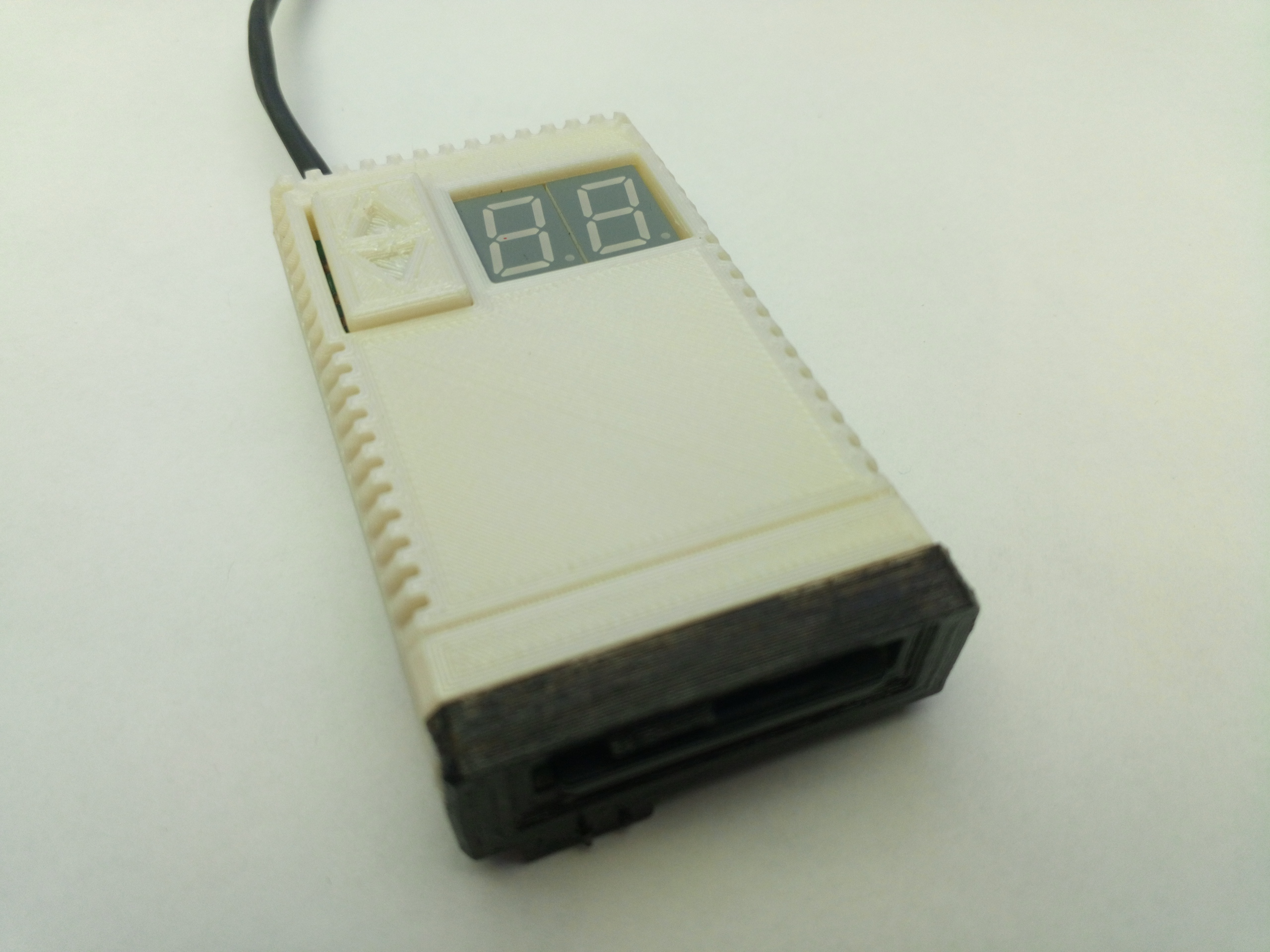
For a more polished product, I have designed a PCB that can fit into a 3D-printed case that resembles a tiny floppy drive with the SD card acting as a tiny floppy disk.
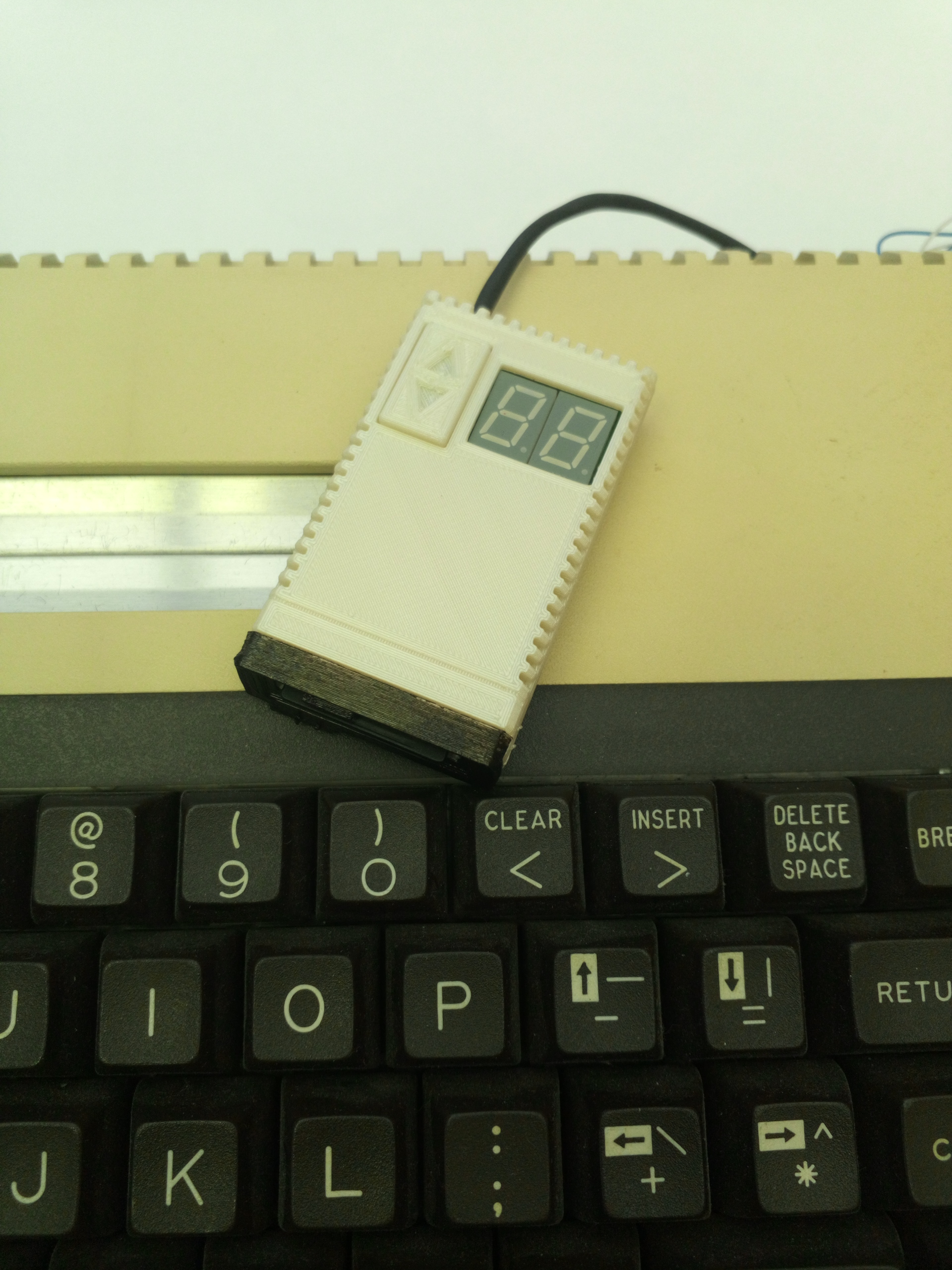
The floppy drive emulator needs an SDcard containing .ats files for each individual floppy disk. Because there is no elaborated user-interface on the device, the naming and location of the files need to follow a fixed system: The files are searched for in a directory ATARI/ on the root of the SDcard. Every disk file must be named nn_Anything.ats with two leading digits that correspond to the numeric display on the device and the mandatory '_' character. Alternatively you can also have a folder named nn_Anything with individual files inside. Such a folder will be emulated as an read-only enhanced density floppy containing these files.
Currently only a very basic support for single density (720 sectors) and enhanced density (1040 sectors) floppies is provided without special functions for any third-party devices.
You can switch though the numbered disks 00 to 99 with the two buttons. This is the maximum number of disks supported on a single SDcard. When you switch beyond 99, you will see -- on the display, which means the device now emulates a switched off floppy drive. Selecting a number for which no diskfile exists will simulate a device with no floppy inserted (in this case you can create a diskfile with the DOS format functions).
You can also emulate a second floppy drive, which is very usable for example for holding the save disks for games that support this. To do so, you need to press both buttons to make the small indicator dot appear on the left LCD block. This means that the number you see in the display is the floppy that is inserted in drive 2. This floppy can now also be changed with the two buttons. It is even possible to select the same floppy in both drives at once (but this is probably of no great use).
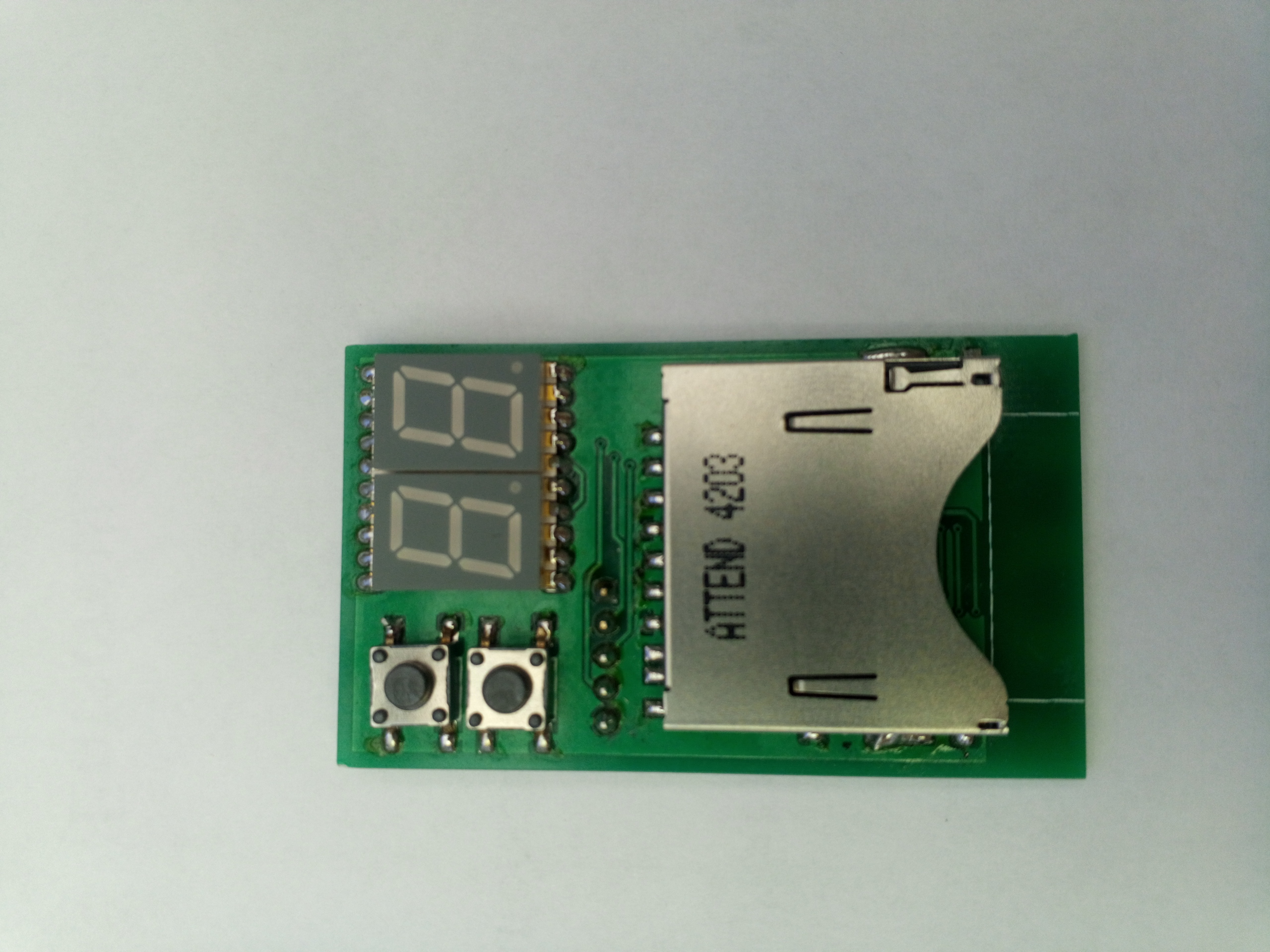
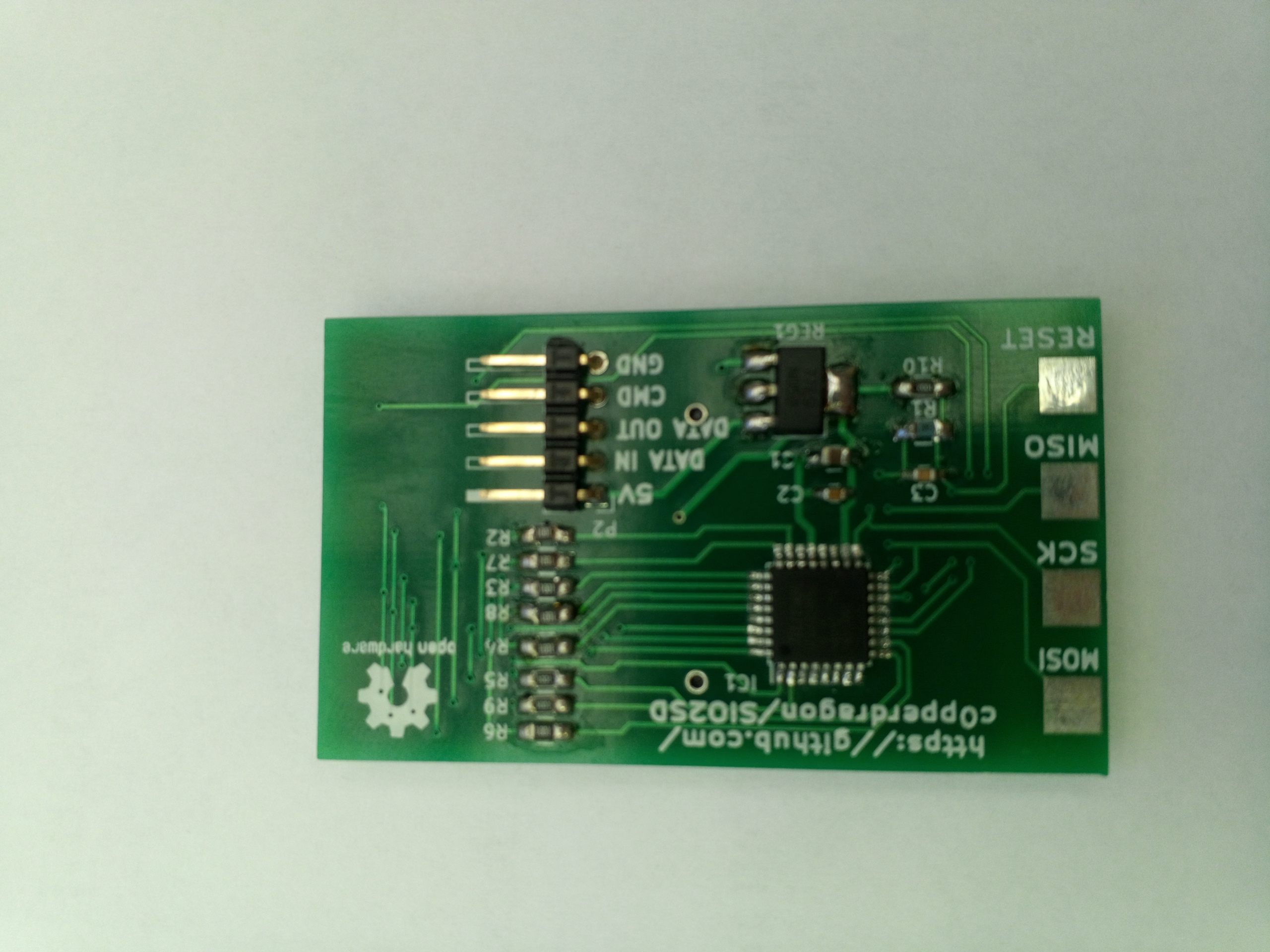
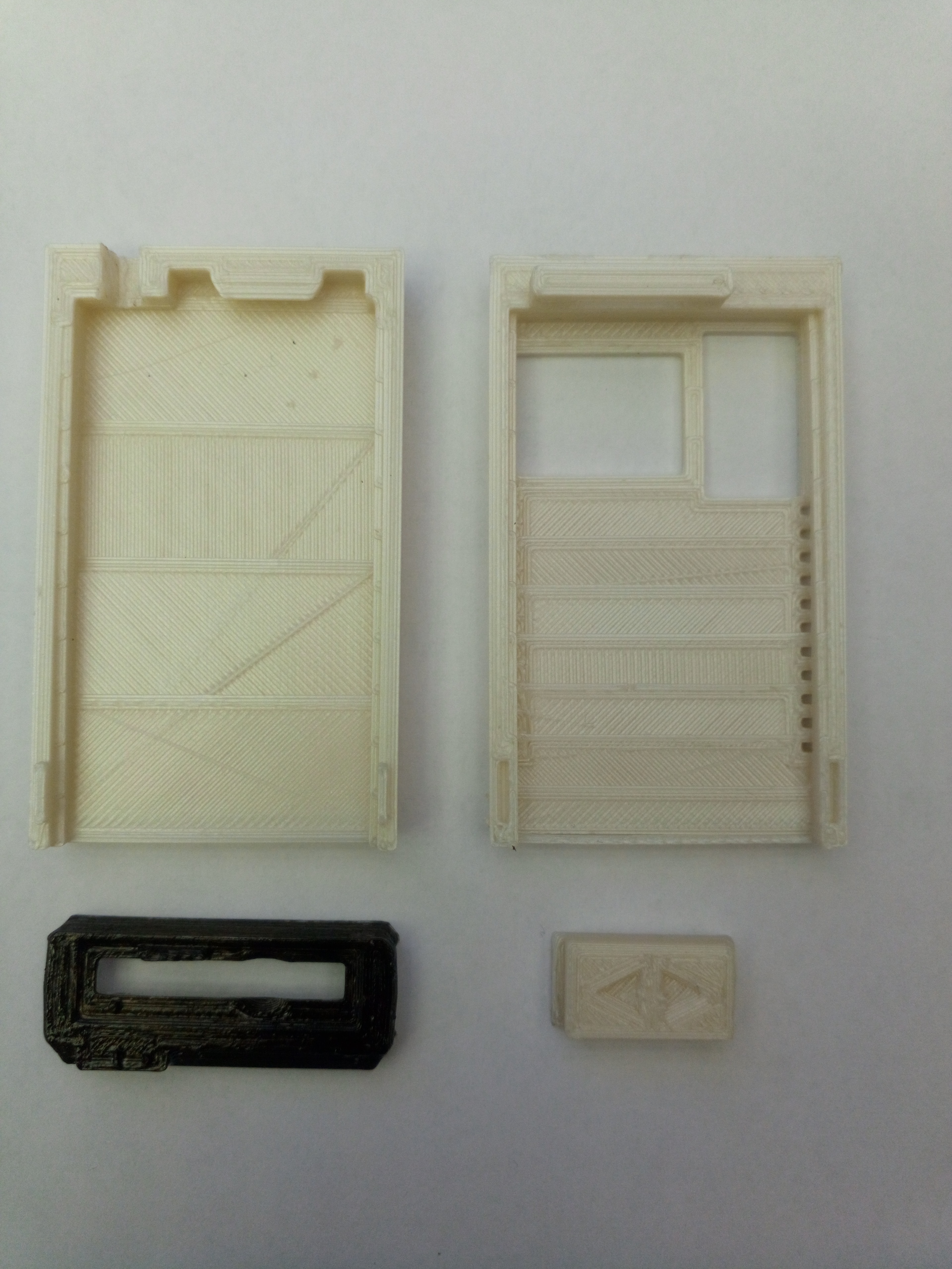
My brother went to greate lengths, designing a proper case for the floppy emulator. In my oppinion, this now looks absolutely phantastic.
| Qty | Value | Footprint | References |
|---|---|---|---|
| 8 | 1k | Resistor_SMD:R_0805_2012Metric_Pad1.15x1.40mm_HandSolder | R2, R3, R4, R5, R6, R7, R8, R9 |
| 2 | 100nF | Capacitor_SMD:C_0603_1608Metric_Pad1.05x0.95mm_HandSolder | C2, C3 |
| 1 | 0.2V | Diode_SMD:D_0805_2012Metric_Pad1.15x1.40mm_HandSolder | D1 |
| 1 | 10k | Resistor_SMD:R_0805_2012Metric_Pad1.15x1.40mm_HandSolder | R10 |
| 1 | 10uF | Capacitor_SMD:C_0805_2012Metric_Pad1.15x1.40mm_HandSolder | C1 |
| 1 | 220k | Resistor_SMD:R_0805_2012Metric_Pad1.15x1.40mm_HandSolder | R1 |
| 1 | ATMEGA328PB-A | Package_QFP:TQFP-32_7x7mm_P0.8mm | IC1 |
| 1 | DOWN | footprints:button | SW2 |
| 1 | LED2DIGIT | footprints:led2digit | LED1 |
| 1 | LM1117IMPX-3.3 | Package_TO_SOT_SMD:SOT-223 | REG1 |
| 1 | MISO | footprints:pad | W2 |
| 1 | MOSI | footprints:pad | W1 |
| 1 | Reset | footprints:pad | W4 |
| 1 | SCK | footprints:pad | W3 |
| 1 | SD_Card | footprints:sdcardsocket | CON1 |
| 1 | SIO | Connector_PinHeader_2.54mm:PinHeader_1x05_P2.54mm_Horizontal | P2 |
| 1 | UP | footprints:button | SW1 |
The 25 most common of 26 parts.
It measures 58.4 × 34.3 mm and has 2 copper layers, 1.6 mm thick.
26 parts, built around the ATMEGA328PB-AU and LM1117IMPX-3.3. The full list of its parts is on this page, with links to each part's symbol and footprint where PCBKit's library has them.
From the c0pperdragon/SIO2SD repository on GitHub, at the commit this page was made from: the board is board/sio2sd.kicad_pcb. PCBKit opens the board in the browser, with nothing to install.
Its repository states no licence, so its author keeps all rights: ask c0pperdragon before reusing the design.
c0pperdragon/C64-Video-Enhancement
Component video modification for the C64 8-bit computer

c0pperdragon/A-VideoBoard
FPGA board to create a component video signal for vintage computers.

c0pperdragon/ZX-Spectrum-Component-Video
Component video (YPbPr) output for the ZX Spectrum computer


aweeri/Control-Avionics-RP2350
Control Avionics RP2350 [CARP] is a compact system designed specifically for operating small scale sounding rockets.


kiu/lofence
LoFence is a LoRaWAN capable IoT electric fence monitoring system running on the The Things Network.