2 layers61 × 64.1 mm
Rfreplacement
c0pperdragon/C64-Video-Enhancement
Component video modification for the C64 8-bit computer
98 parts286MIT
 qeda/examples
PCB examples with using QEDA
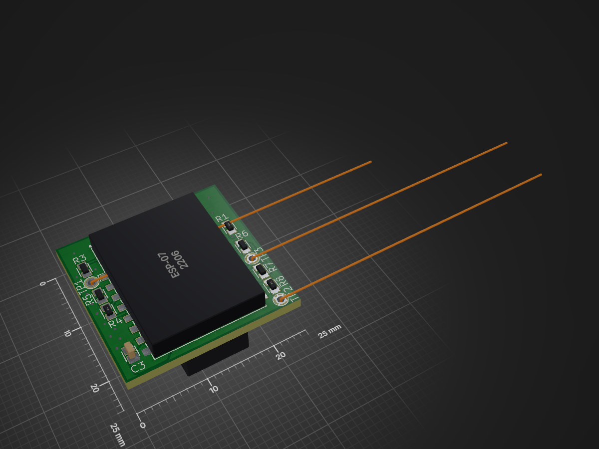
Wifi adapter is an open-source printed circuit board by qeda, from the qeda/examples repository on GitHub, published under the MIT licence. It is a 2-layer board of 25 × 25 mm with 17 parts on 13 nets, routed with 164 tracks and 48 vias.
It is built around the ESP-07, LM1117IMPX-3.3 and DF13A-6P-1.25H. Its parts include 8 resistors, 3 capacitors, 2 ICs and 1 connector. It belongs with the radio and wireless and interfaces and adapters boards and the ESP8266 boards of this library.


Here you will find PCB examples made using QEDA.
This is a simple adapter allowing to connect ESP-07 Wi-Fi module to Pixhawk autopilot.
All source files are licensed under MIT license.
| Qty | Value | Footprint | References |
|---|---|---|---|
| 4 | DNP | wa:RESC1608X55M | R3, R5, R6, R7 |
| 2 | 10k | wa:RESC1608X55M | R4, R8 |
| 2 | 10u | wa:CAPC3225X230M | C1, C2 |
| 2 | 33 | wa:RESC1608X55M | R1, R2 |
| 1 | 0.1u | wa:CAPC1608X92M | C3 |
| 1 | DF13A-6P-1.25H | wa:HIROSE_DF13A-6P-1.25H | J1 |
| 1 | ESP-07 | wa:SON200P2120X1600X300-16M | U2 |
| 1 | GND | wa:TP-TH-1 | TP2 |
| 1 | GP0 | wa:TP-TH-1 | TP3 |
| 1 | LM1117IMPX-3.3 | wa:SOT230P700X180-4M | U1 |
| 1 | RST | wa:TP-TH-1 | TP1 |
It measures 25 × 25 mm and has 2 copper layers, 1.6 mm thick.
17 parts, built around the ESP-07, LM1117IMPX-3.3 and DF13A-6P-1.25H. The full list of its parts is on this page, with links to each part's symbol and footprint where PCBKit's library has them.
From the qeda/examples repository on GitHub, at the commit this page was made from: the board is wifi-adapter/board/wifi-adapter.kicad_pcb. PCBKit opens the board in the browser, with nothing to install.
Its repository publishes it under the MIT licence: you may reuse it on that licence's terms (keep the author's notice, and for a copyleft licence share your changes alike).
c0pperdragon/C64-Video-Enhancement
Component video modification for the C64 8-bit computer

c0pperdragon/SIO2SD
An Arduino-based floppy drive emulator for the atari 8 bit computers.

c0pperdragon/A-VideoBoard
FPGA board to create a component video signal for vintage computers.

c0pperdragon/ZX-Spectrum-Component-Video
Component video (YPbPr) output for the ZX Spectrum computer


aweeri/Control-Avionics-RP2350
Control Avionics RP2350 [CARP] is a compact system designed specifically for operating small scale sounding rockets.


GonzaCerv/noah-hardware
This repo contains all the hardware description for the Noah project. Here lies 3D models, electronics PCB and Firmware software of the robot.