2 layers53.3 × 22.9 mm
WsprryPico Synth Shield with GPS
WsprryPi/WsprryPi-PCB-Designs
HAT and LPF Designs for the WsprryPi Organization
46 parts1MIT

 ckuhtz/picise
Prototype for a time / location GNSS accessory for a Raspberry Pi 40-pin GPIO.
Picise is an open-source printed circuit board by ckuhtz, from the ckuhtz/picise repository on GitHub, published under the CC-BY-SA-4.0 licence. It is a 2-layer board of 65 × 23.5 mm with 39 parts on 59 nets, routed with 297 tracks and 63 vias.
It is built around the MAX-M10S-00B, CAT24C256WI-GT3 and PCA9557PW, with the CC0603KRX7R9BB104, SD0603S040S0R2 and LQW18AN47NG00D among its other parts. Its parts include 12 resistors, 11 capacitors, 3 ICs, 3 diodes and 2 connectors. It belongs with the radio and wireless boards of this library.


Prototype for a time / location accessory for a Raspberry Pi 40-pin GPIO.
Vertical GPIO riser with
2022-11-25: rev2 design in progress.
2022-11-24: rev1 assembled, working (click on video below). Planning rev2 improvements.
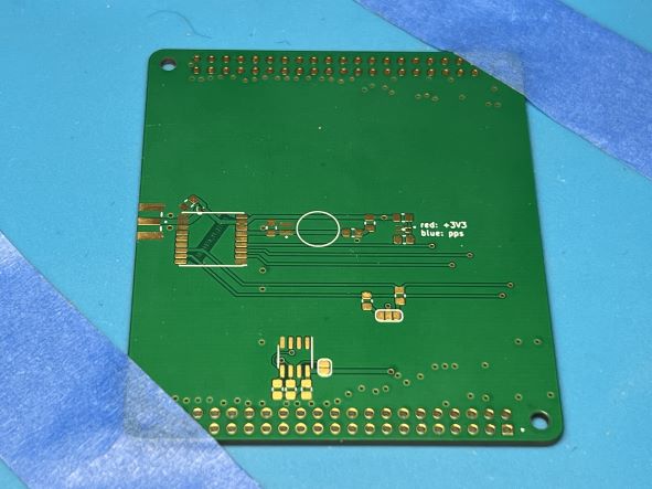
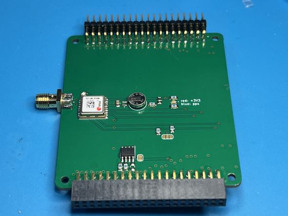

2022-11-01: rev1 prototype boards received, pending assembly.
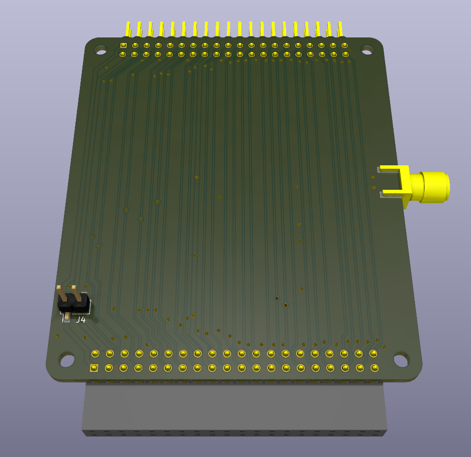
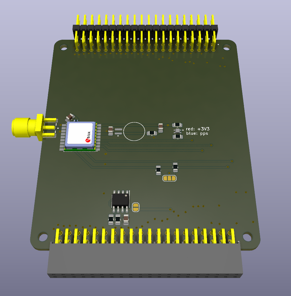
Library not published at this time. Can't remember what has which licensing where I used stuff from vendors.
CC BY-SA 4.0, see LICENSE file.
| Qty | Value | Footprint | References |
|---|---|---|---|
| 3 | 0.1uF | Capacitor_SMD:C_0603_1608Metric | C4, C8, C9 |
| 3 | 10uF | Capacitor_SMD:C_0603_1608Metric | C2, C5, C6 |
| 3 | 1uF | Capacitor_SMD:C_0603_1608Metric | C3, C7, C14 |
| 3 | 20k | Resistor_SMD:R_0603_1608Metric | R3, R4, R5 |
| 2 | 2k2 | Resistor_SMD:R_0603_1608Metric | R11, R12 |
| 2 | 3.9k | Resistor_SMD:R_0603_1608Metric | R6, R7 |
| 2 | MountingHole_2.7mm_M2.5 | MountingHole:MountingHole_2.7mm_M2.5 | MH1, MH2 |
| 1 | 0.5A 40V 420mV | Diode_SMD:D_0603_1608Metric | D25 |
| 1 | 10R | Resistor_SMD:R_0603_1608Metric | R1 |
| 1 | 22pF | Capacitor_SMD:C_0603_1608Metric | C15 |
| 1 | 330R | Resistor_SMD:R_0603_1608Metric | R8 |
| 1 | 47nH | Inductor_SMD:L_0603_1608Metric | L1 |
| 1 | 47pF | Capacitor_SMD:C_0603_1608Metric | C1 |
| 1 | 620R | Resistor_SMD:R_0603_1608Metric | R10 |
| 1 | 80R | Resistor_SMD:R_0603_1608Metric | R9 |
| 1 | ANT_SMA | Connector_SMA_Samtec:SAMTEC_SMA-J-P-H-ST-EM1 | J1 |
| 1 | Blue | Diode_SMD:D_0603_1608Metric | D69 |
| 1 | CAT24C256 | Package_SO:SOIC-8_3.9x4.9mm_P1.27mm | U3 |
| 1 | DNP | Resistor_SMD:R_0805_2012Metric_Pad1.20x1.40mm_HandSolder | R2 |
| 1 | ID_WP | Jumper:SolderJumper-2_P1.3mm_Open_RoundedPad1.0x1.5mm | JP2 |
| 1 | LOGO | Graphics:by-sa 15x5.2 | |
| 1 | MAX-M10S | RF_GNSS_u-blox:MAX-M10S | U1 |
| 1 | MS621FE-FL11E | Battery_Cell_Seiko:BAT_MS621FE-FL11E | BT1 |
| 1 | PCA9557PW | Package_SO:TSSOP-16_4.4x5mm_P0.65mm | U2 |
| 1 | Red | Diode_SMD:D_0603_1608Metric | D42 |
| 1 | SSQ-120-03_GPIO | Connector_Header_Samtec:SAMTEC_SSQ-120-03-G-D_Pi | J2 |
| 1 | SolderJumper_3_Open | Jumper:SolderJumper-3_P1.3mm_Open_RoundedPad1.0x1.5mm | JP3 |
The 38 most common of 39 parts.
It measures 65 × 23.5 mm and has 2 copper layers, 1.6 mm thick.
39 parts, built around the MAX-M10S-00B, CAT24C256WI-GT3, PCA9557PW and CC0603KRX7R9BB104. The full list of its parts is on this page, with links to each part's symbol and footprint where PCBKit's library has them.
From the ckuhtz/picise repository on GitHub, at the commit this page was made from: the board is picise.kicad_pcb and its schematic picise.kicad_sch. PCBKit opens the board in the browser, with nothing to install.
Its repository publishes it under the CC-BY-SA-4.0 licence: you may reuse it on that licence's terms (keep the author's notice, and for a copyleft licence share your changes alike).
WsprryPi/WsprryPi-PCB-Designs
HAT and LPF Designs for the WsprryPi Organization

nherbaut/pico-power-sensor
This board sockets a Pico 2 W, provides five programmable green LEDs and a microSD slot, and connects to the INA229EVM through a left-edge right-angle socket.

LulaUAV/Strelka-Flight-Computer
Strelka exists in the family of rocket dog flight computers. This flight computer is fully capable of deploying recovery events.


wildjames/smart_compass
The product is going to be something similar to the compass in the Pirates of the Caribbean.

UltimateHackingKeyboard/uhk60v1-electronics
The schematic and PCBs of the UHK 60 v1

UltimateHackingKeyboard/uhk60v2-electronics
The electronics files of the UHK 60 v2
