2 layers80 × 21 mm
Epoch Mainboard
CircuitMonkey/epoch-2
Epoch Vibrator Controller 2 - Now with 100% more edge...
48 partsMIT

 CircuitMonkey/epoch-2
Epoch Vibrator Controller 2 - Now with 100% more edge...
Output Test Board is an open-source printed circuit board by CircuitMonkey, from the CircuitMonkey/epoch-2 repository on GitHub, published under the MIT licence. It is a 2-layer board of 31.4 × 14 mm with 16 parts on 13 nets, routed with 78 tracks and 35 vias.
It is built around the NRVA4007T3G-JSM, SI1308EDL and MF-MSMF075. Its parts include 6 resistors, 4 diodes, 2 transistors, 2 connectors and 1 capacitor.


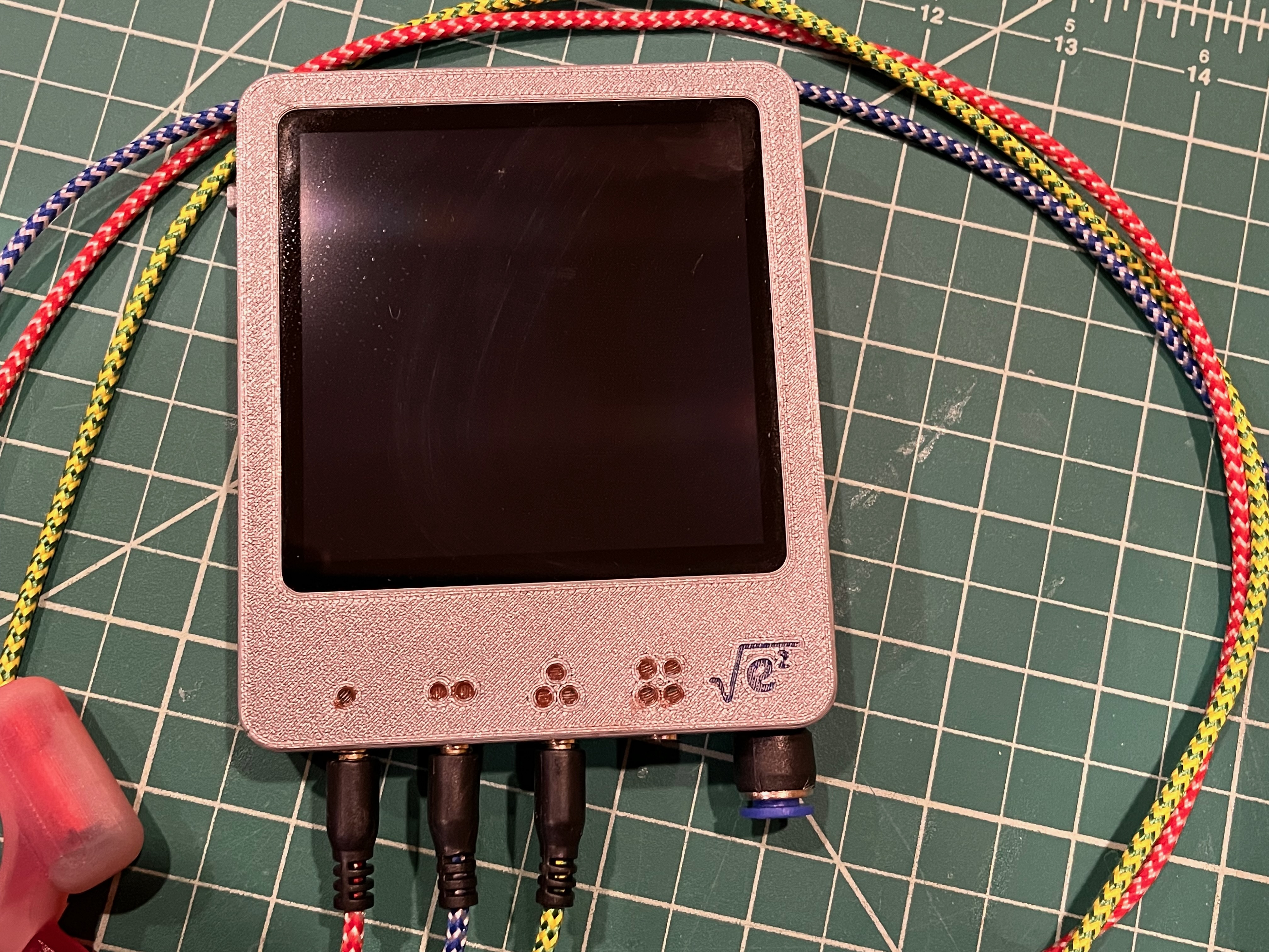
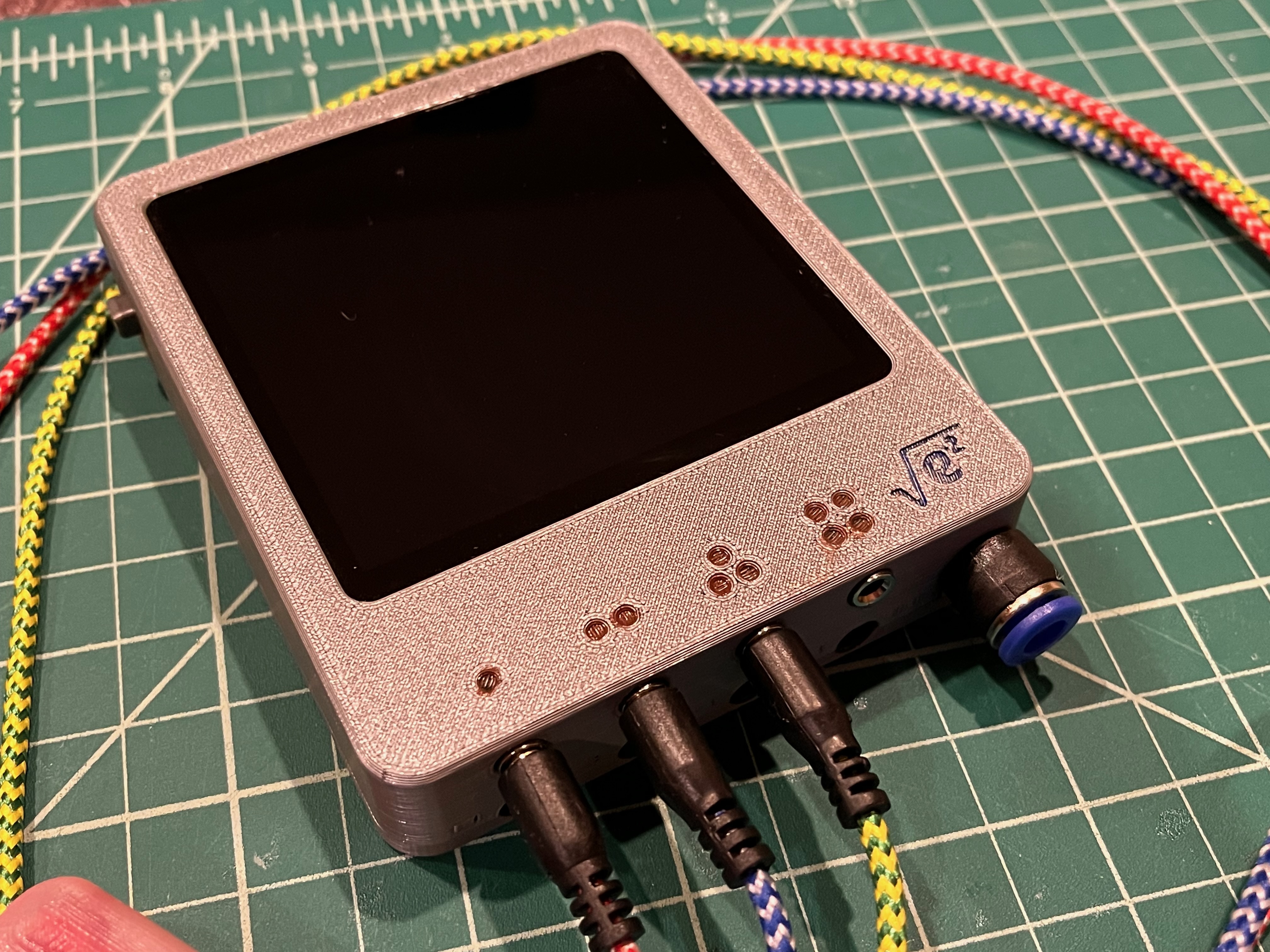
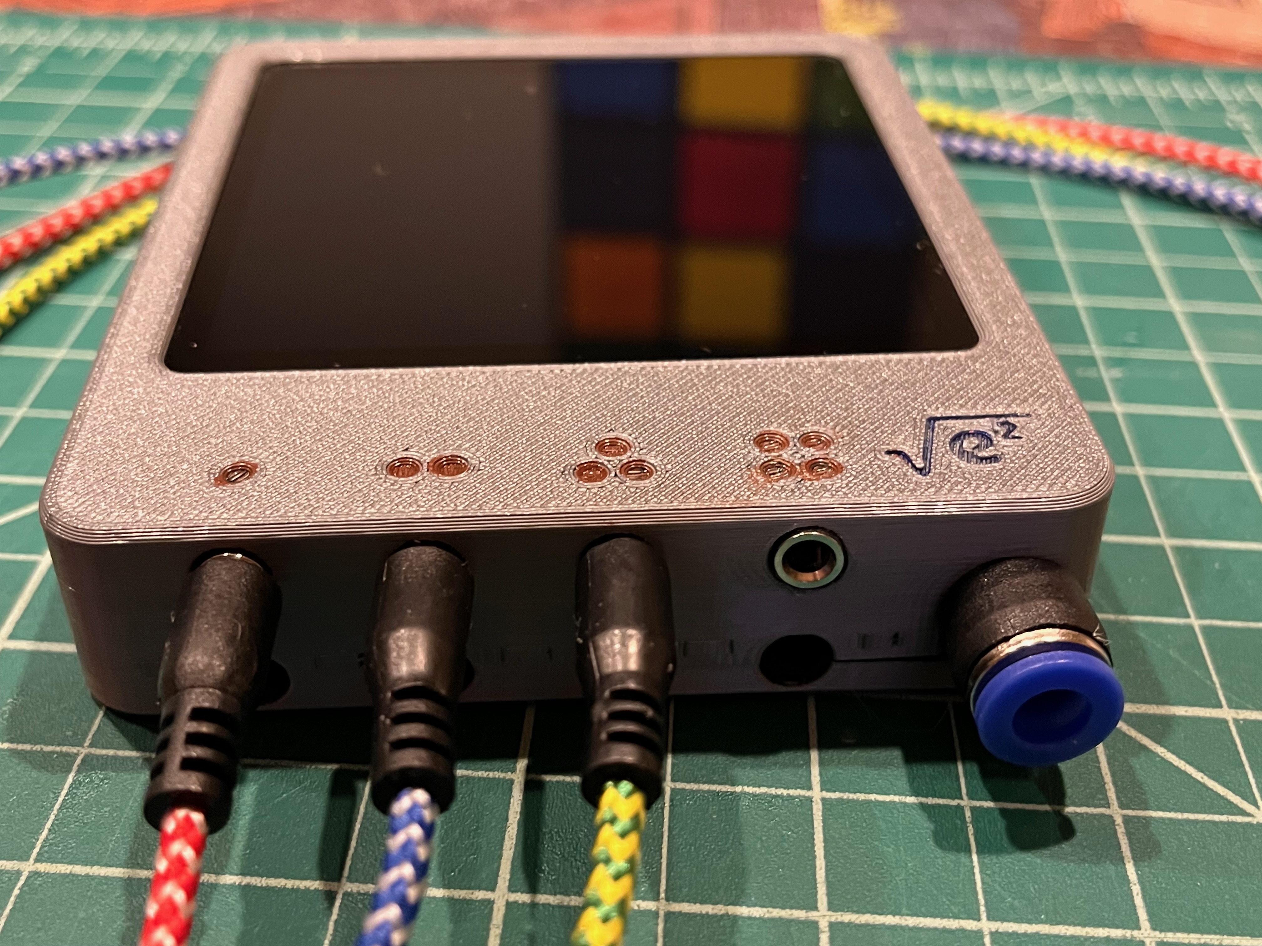
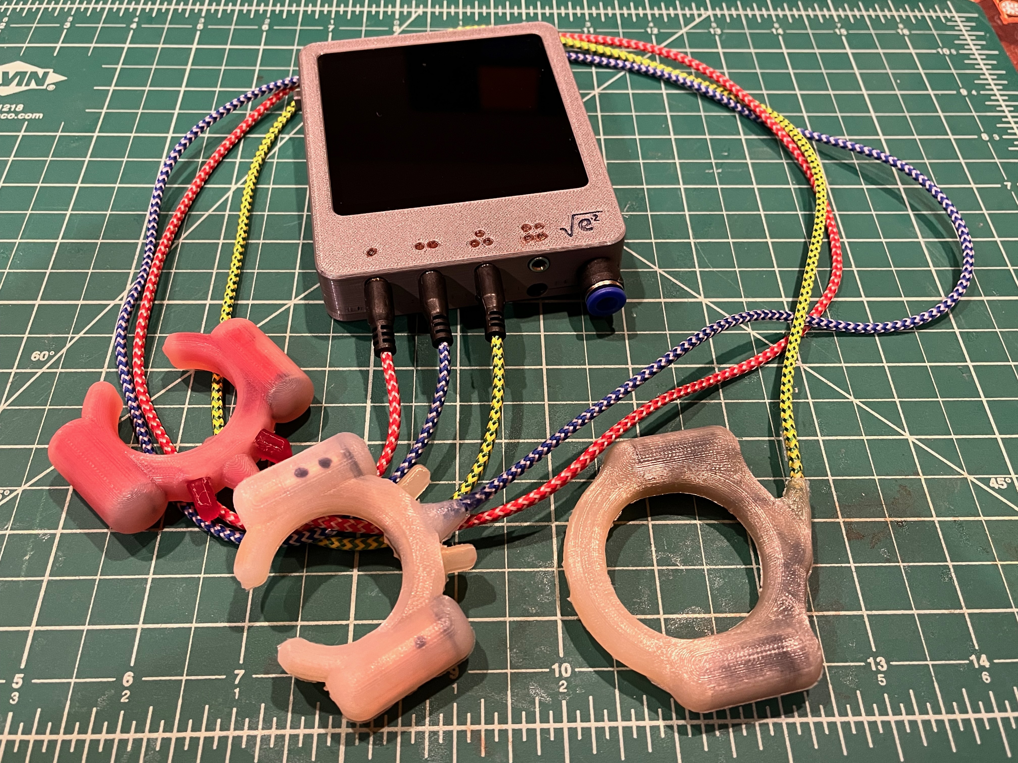
Epoch Vibrator Controller (Haptic Field Emitter) 2 - Now with 100% more edge...
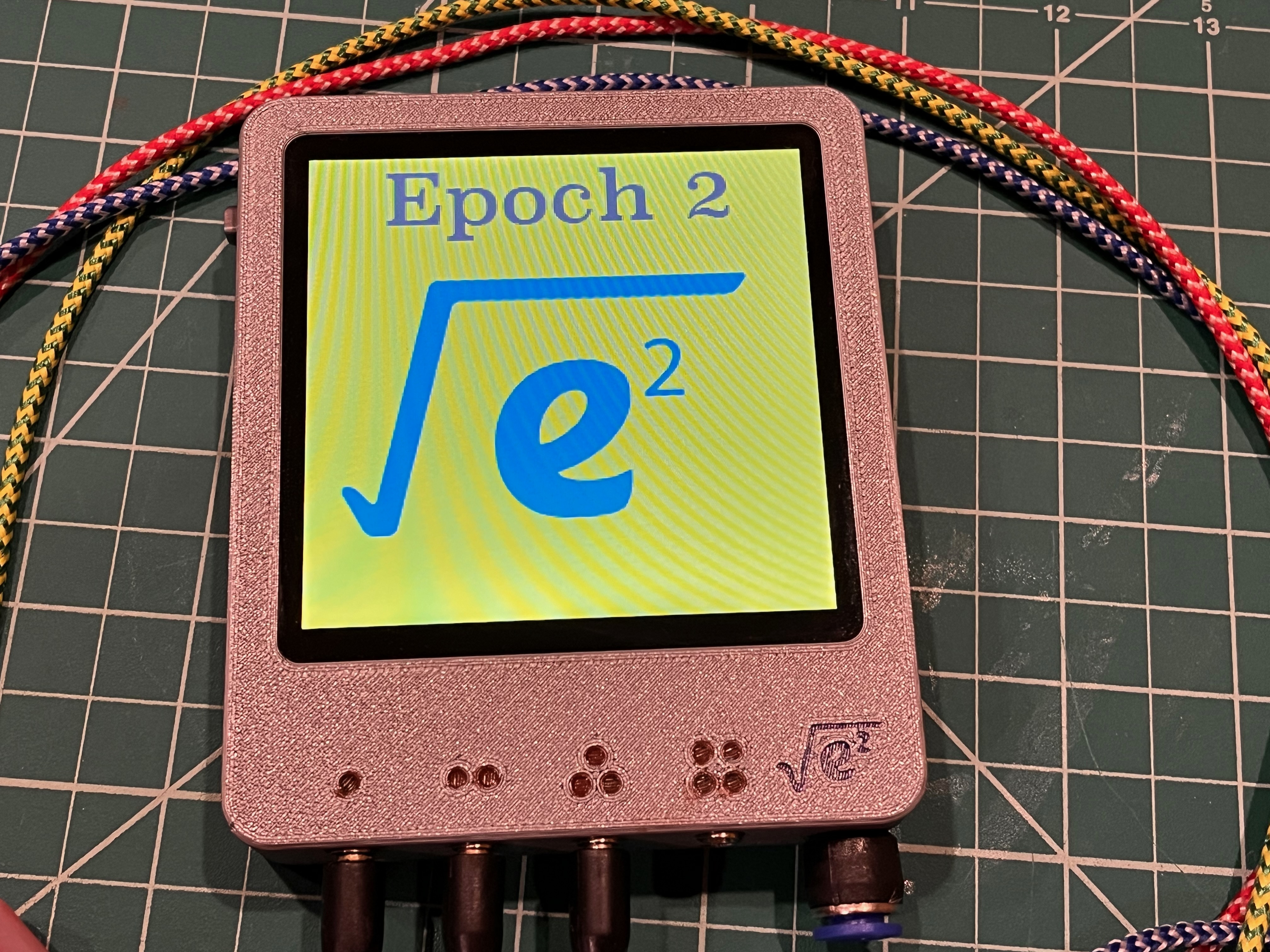
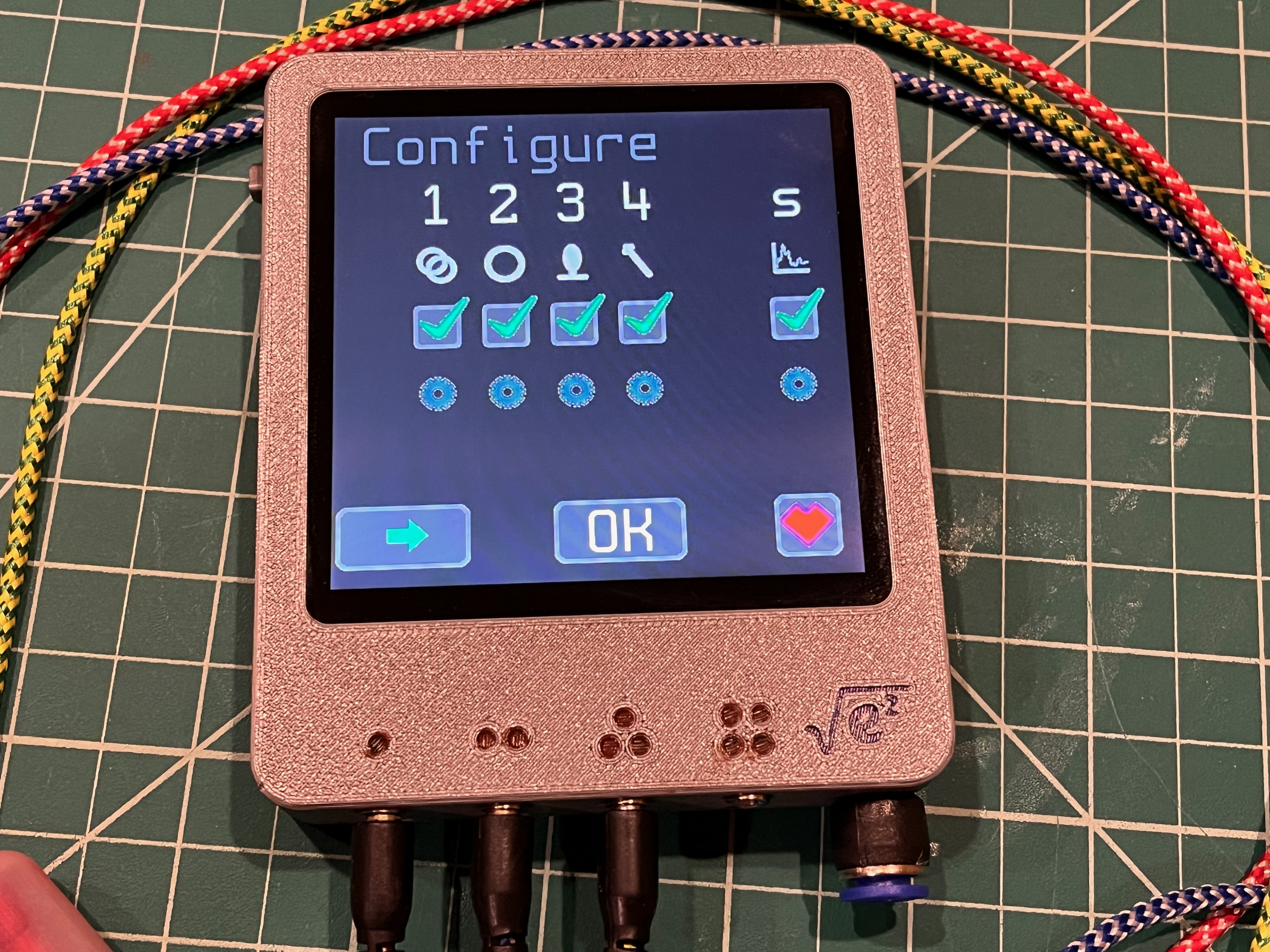
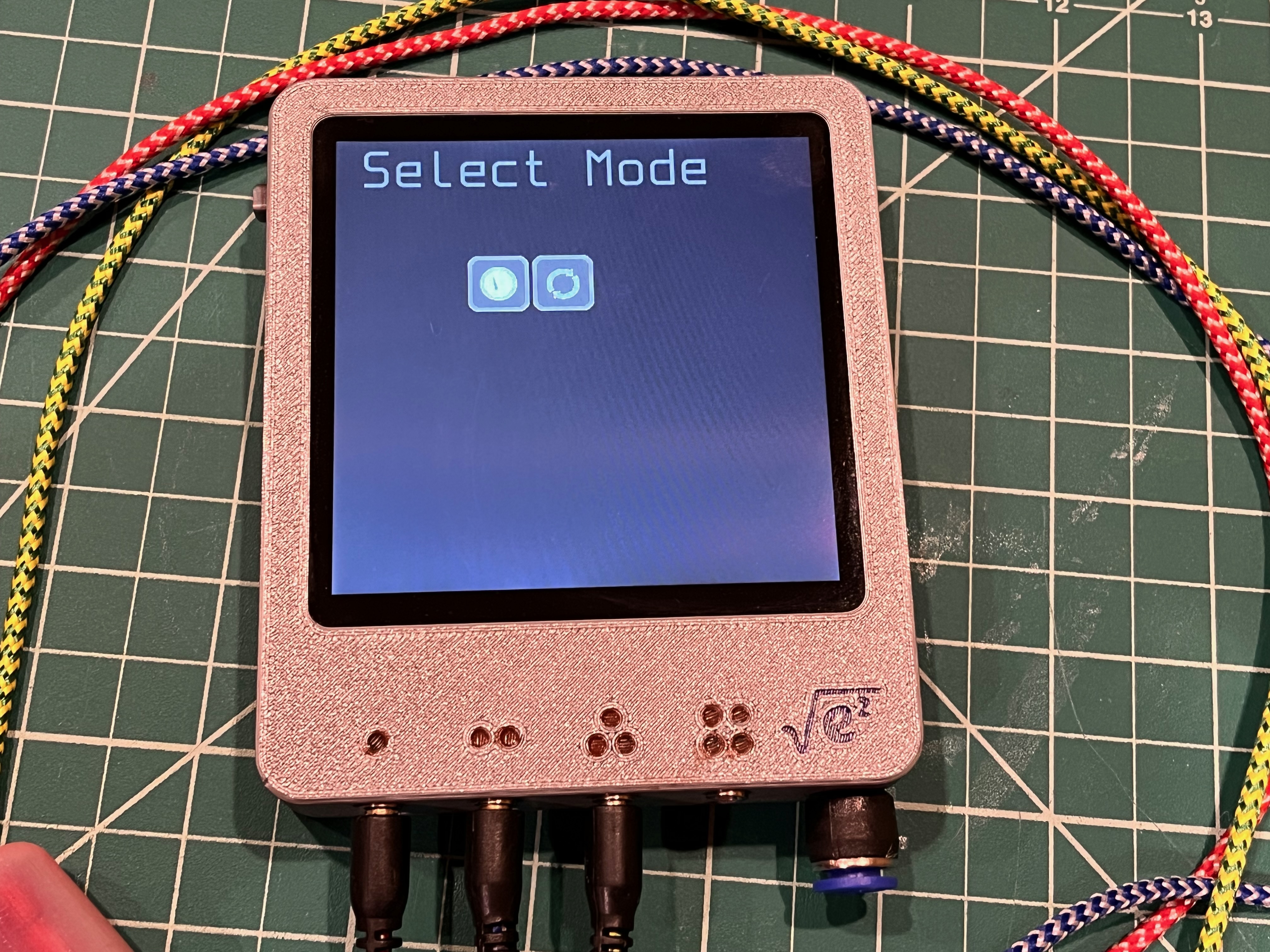
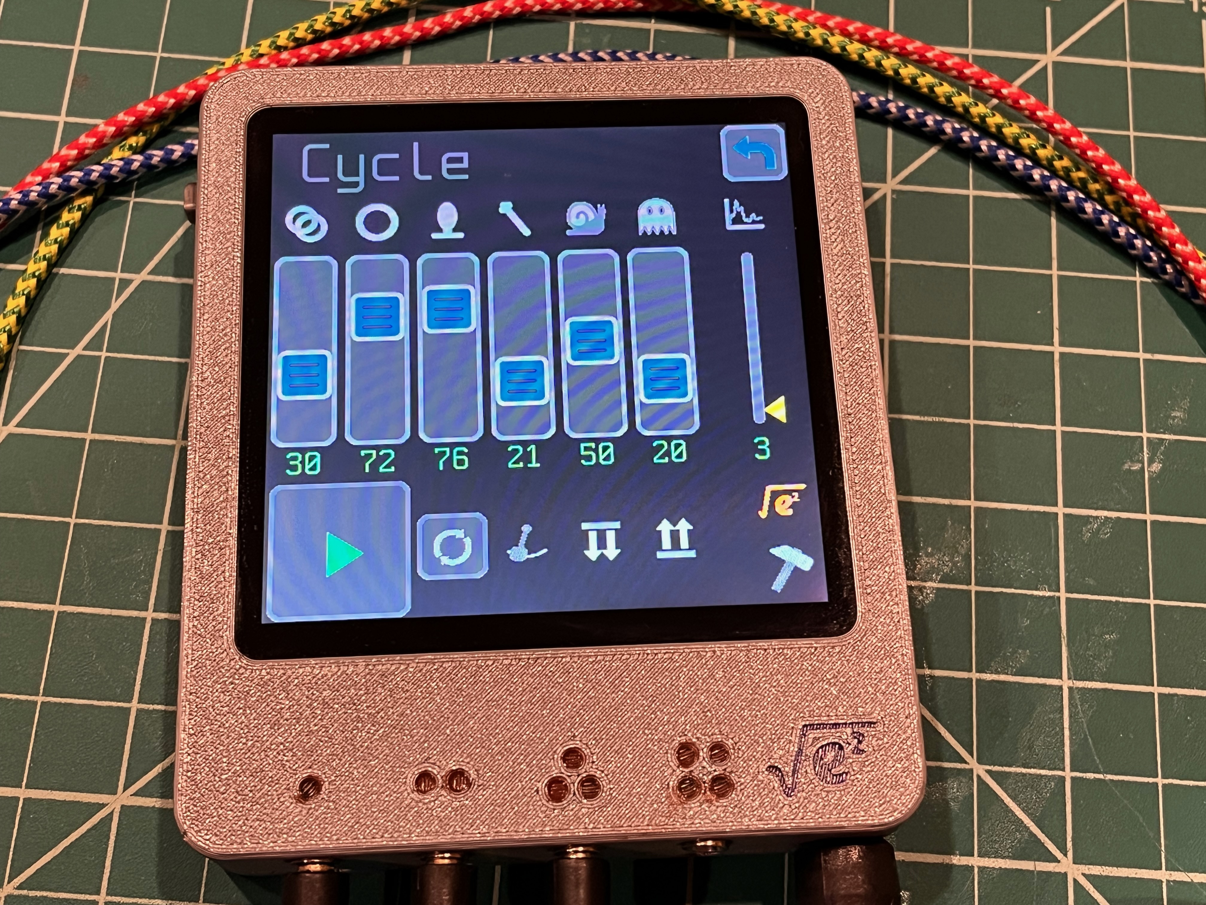
A follow on to Epoch 1. Designed in 2025. Replaced by Epoch 3 in 2026. Redesigned with AdaFruit Qualia ESP32 and a Amazon 4-inch IPS (GT911 touch). Motors driven with pca9685 PWM controller/Amazon PCA9685 Board and FET outputs in order to drive bigger motors. Epoch 1 was limited to 120mA maximum motor drive (because of PWM controller choice) and some larger "rumble" motors need 180mA or higher.
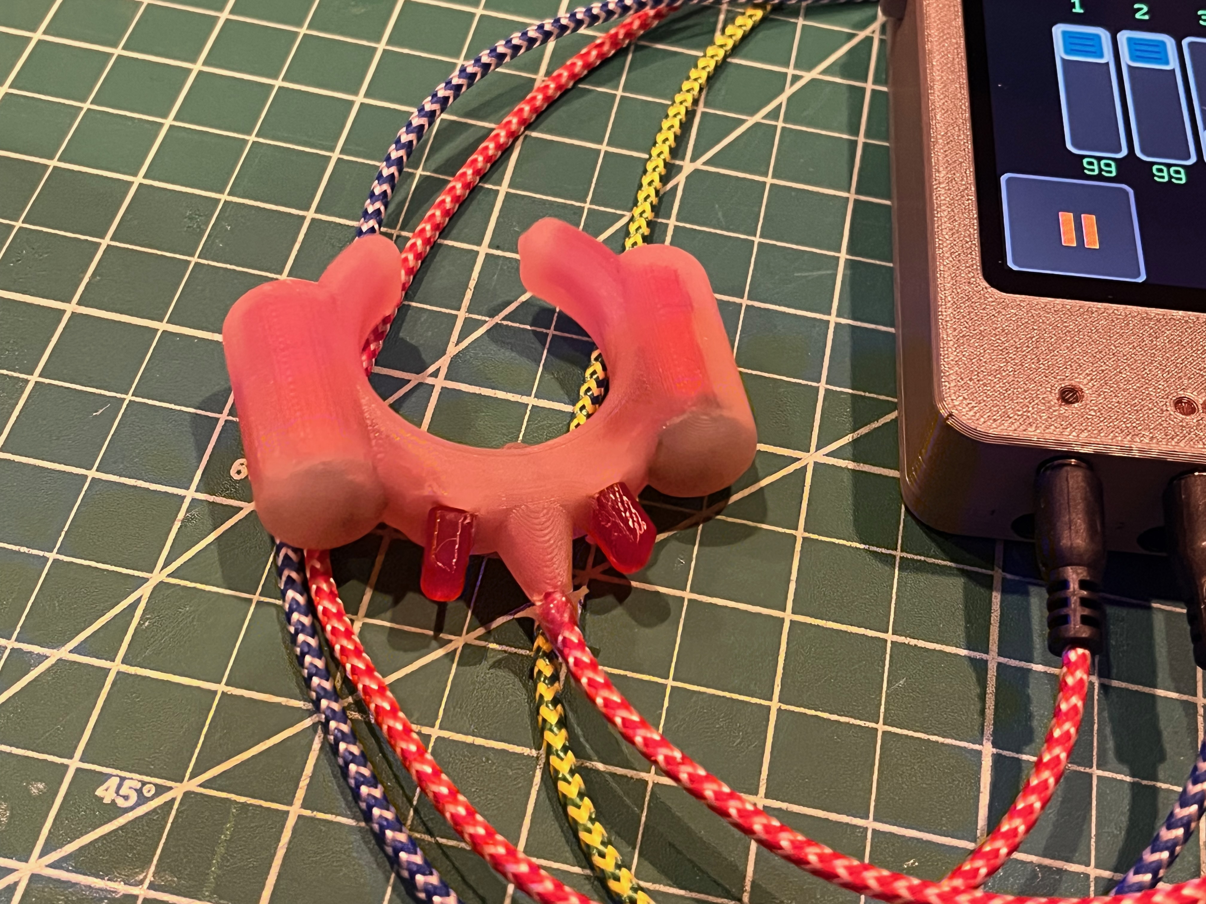
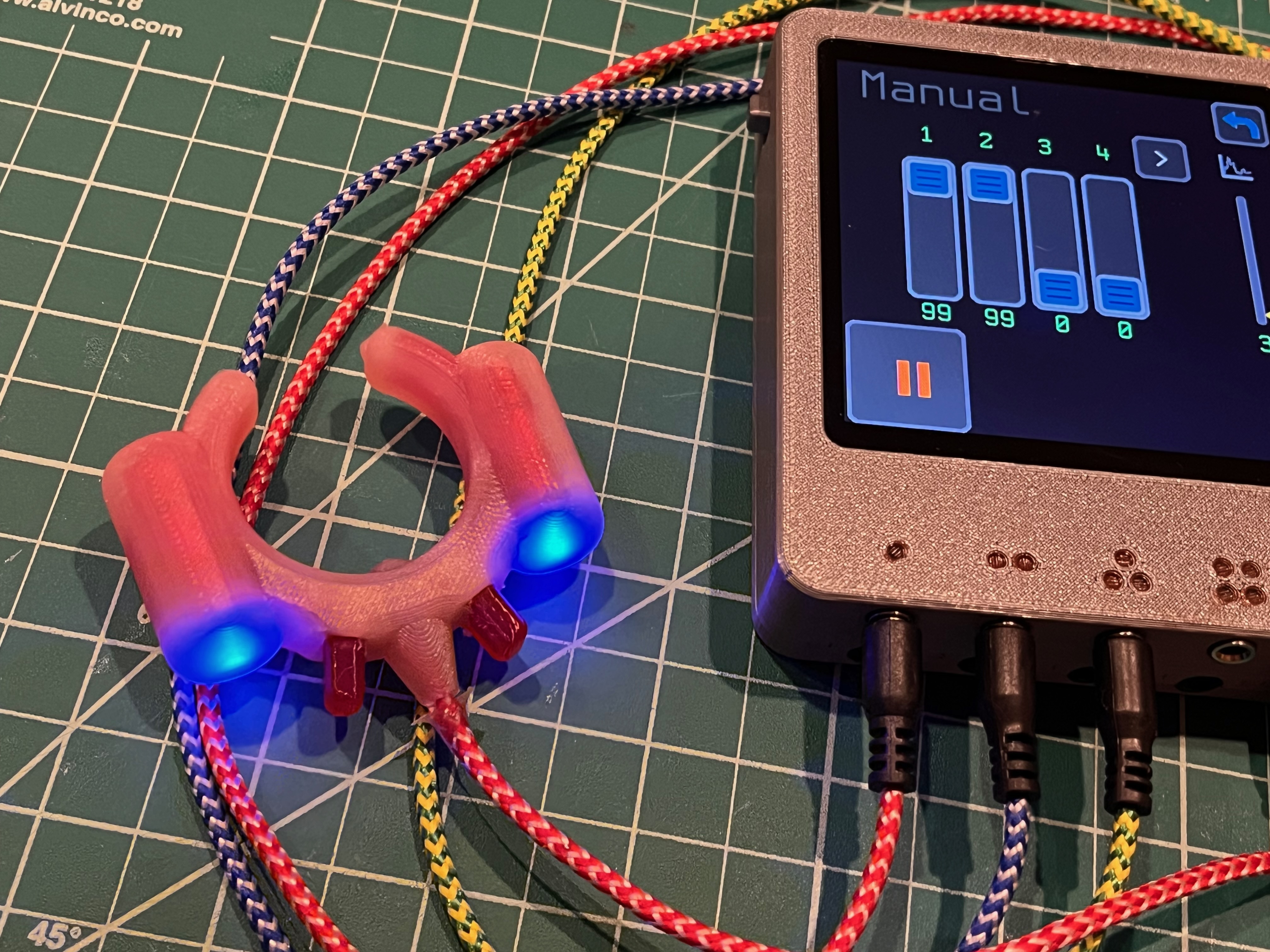
| Qty | Value | Footprint | References |
|---|---|---|---|
| 4 | 220R | Resistor_SMD:R_0603_1608Metric | R1, R2, R3, R4 |
| 2 | 100K | Resistor_SMD:R_0603_1608Metric | R5, R6 |
| 2 | GRN | LED_SMD:LED_0603_1608Metric | D1, D2 |
| 2 | NRVA4007T3G | Diode_SMD:D_SMA | D3, D4 |
| 2 | Si1308EDL | Package_TO_SOT_SMD:SOT-323_SC-70 | Q1, Q2 |
| 1 | 22uF / 16V | Capacitor_SMD:C_1812_4532Metric | C1 |
| 1 | Conn_01x04_Pin | Connector_PinHeader_2.54mm:PinHeader_1x04_P2.54mm_Vertical | J1 |
| 1 | Jack - Tayda A-4780 | Connector_Audio:Jack_3.5mm_Ledino_KB3SPRS_Horizontal | J2 |
| 1 | MF-MSMF075 | Resistor_SMD:R_1812_4532Metric | F1 |
CircuitMonkey/epoch-2
Epoch Vibrator Controller 2 - Now with 100% more edge...

CircuitMonkey/epoch-2
Epoch Vibrator Controller 2 - Now with 100% more edge...

CircuitMonkey/epoch-2
Epoch Vibrator Controller 2 - Now with 100% more edge...

iSebass/MicrocontroladoresTeoria-Practicas
Este repositorio ha sido creado como un recurso de apoyo para el curso de Microcontroladores impartido en la Universidad del Valle. En este espacio colaboraremos con el Dr. en Ingeniería Sergio Arenas y el Ing.


dmatscheko/water_kettle
ESP32-S3 running ESPHome on a custom KiCad PCB for the base of a SEVERIN WK 3479 water kettle


Michael-Manning/E-Paper-Climate-Logger
Firmware, PCB, and enclosure for the Weathergotchi E-Paper climate logger.


gab-k/RP2040-Decoder
Cost effective DIY DCC Decoder for model railroad locomotives
It measures 31.4 × 14 mm and has 2 copper layers, 1.6 mm thick.
16 parts, built around the NRVA4007T3G-JSM, SI1308EDL and MF-MSMF075. The full list of its parts is on this page, with links to each part's symbol and footprint where PCBKit's library has them.
From the CircuitMonkey/epoch-2 repository on GitHub, at the commit this page was made from: the board is PCB/Output-Test-Board/Output-Test-Board.kicad_pcb and its schematic PCB/Epoch-Mainboard/Epoch-Mainboard.kicad_sch. PCBKit opens the board in the browser, with nothing to install.
Its repository publishes it under the MIT licence: you may reuse it on that licence's terms (keep the author's notice, and for a copyleft licence share your changes alike).