2 layers117.3 × 54.5 mm

 chrishoage/spleeb87
A split keyboard... or spleeb
Spleeb is an open-source printed circuit board by chrishoage, from the chrishoage/spleeb repository on GitHub, published under the MIT licence. It is a 2-layer board of 163.1 × 111.9 mm with 69 parts on 54 nets, routed with 598 tracks and 12 vias.
Its parts include 32 diodes and 31 switches. It belongs with the keyboards and input boards of this library.
Another split keyboard... a "Spleeb".
This split keyboard is created using Ergogen and the routing done manually, copied back into the yaml file. This was inspired a lot by the Ergodash which I used for about a year but wanted something that fit my use and hands a bit better.
Photos are pictured with heat set inserts in the bottom chassis that ARE NOT present in the STEP or Fusion 360 files. I was not happy with how the approach I took worked, and didn't want to release something that people may actually use (like the original touchpad bracket which was particularly poorly designed). I didn't want to reprint the bottom just to take some photos. The models in this repo are exactly the same, I just removed the holes for the heat set inserts on the side.
You can read more about the Spleeb Chassis 1.2 revision in the Pull Request which added it.
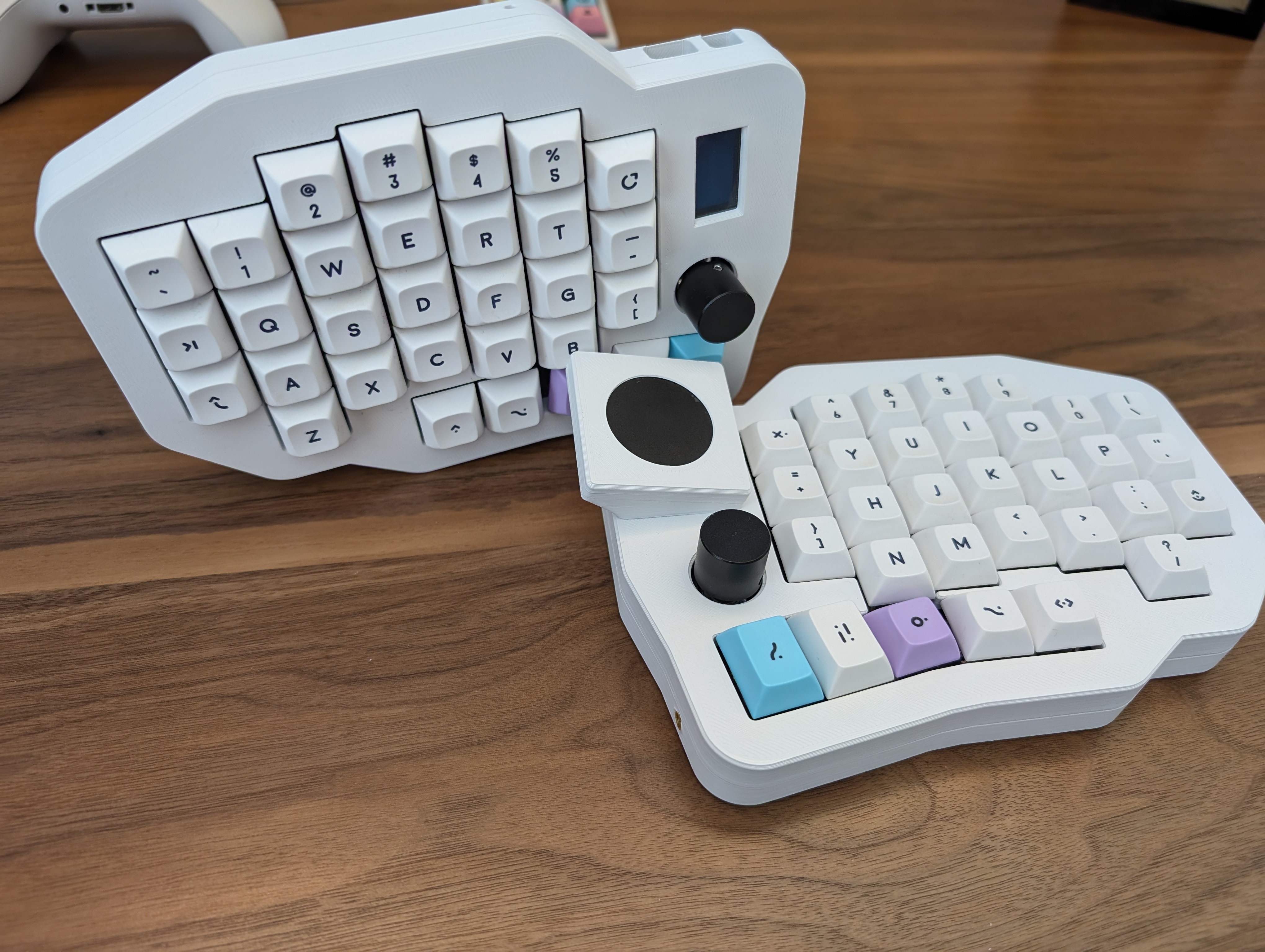
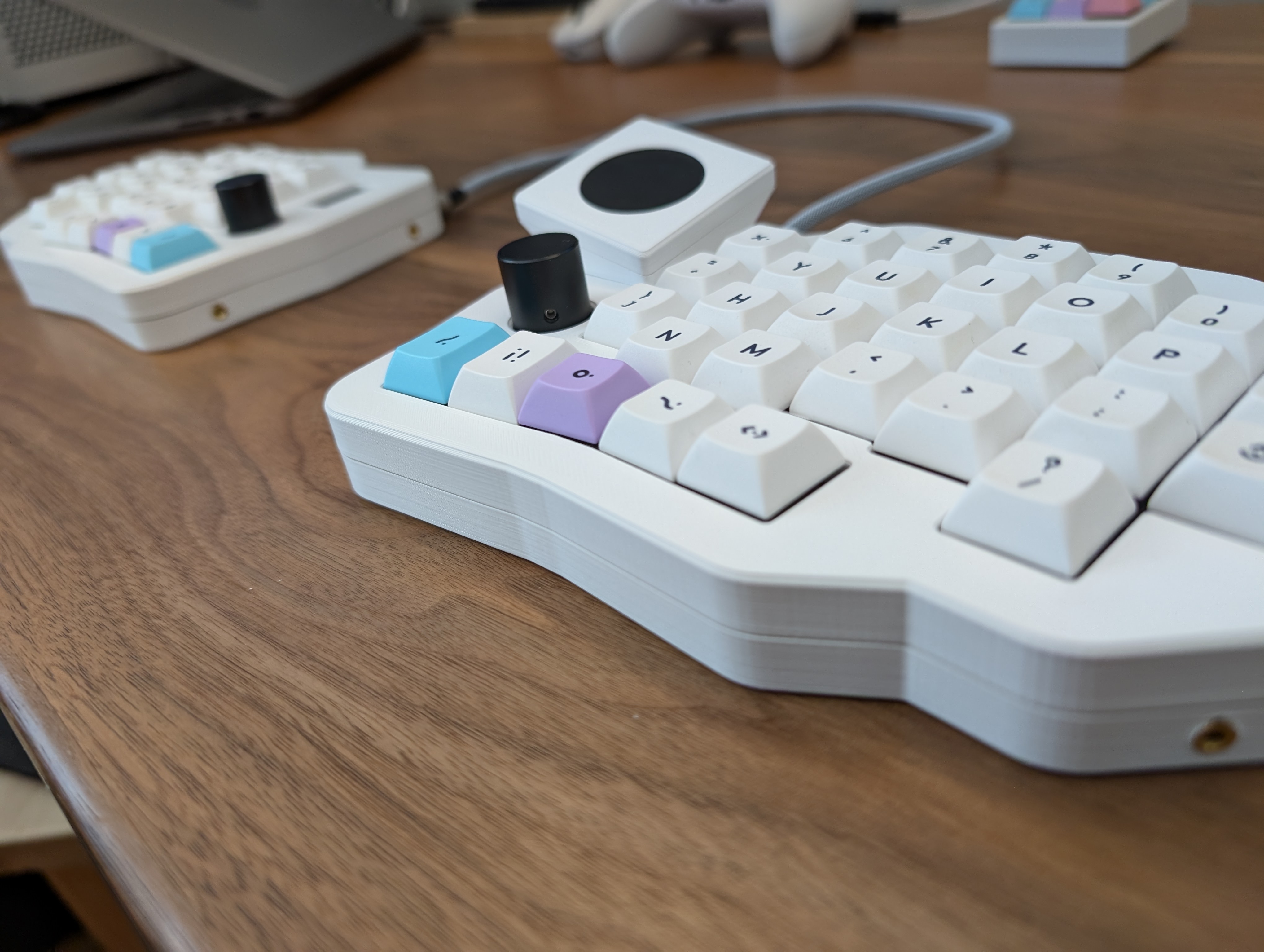
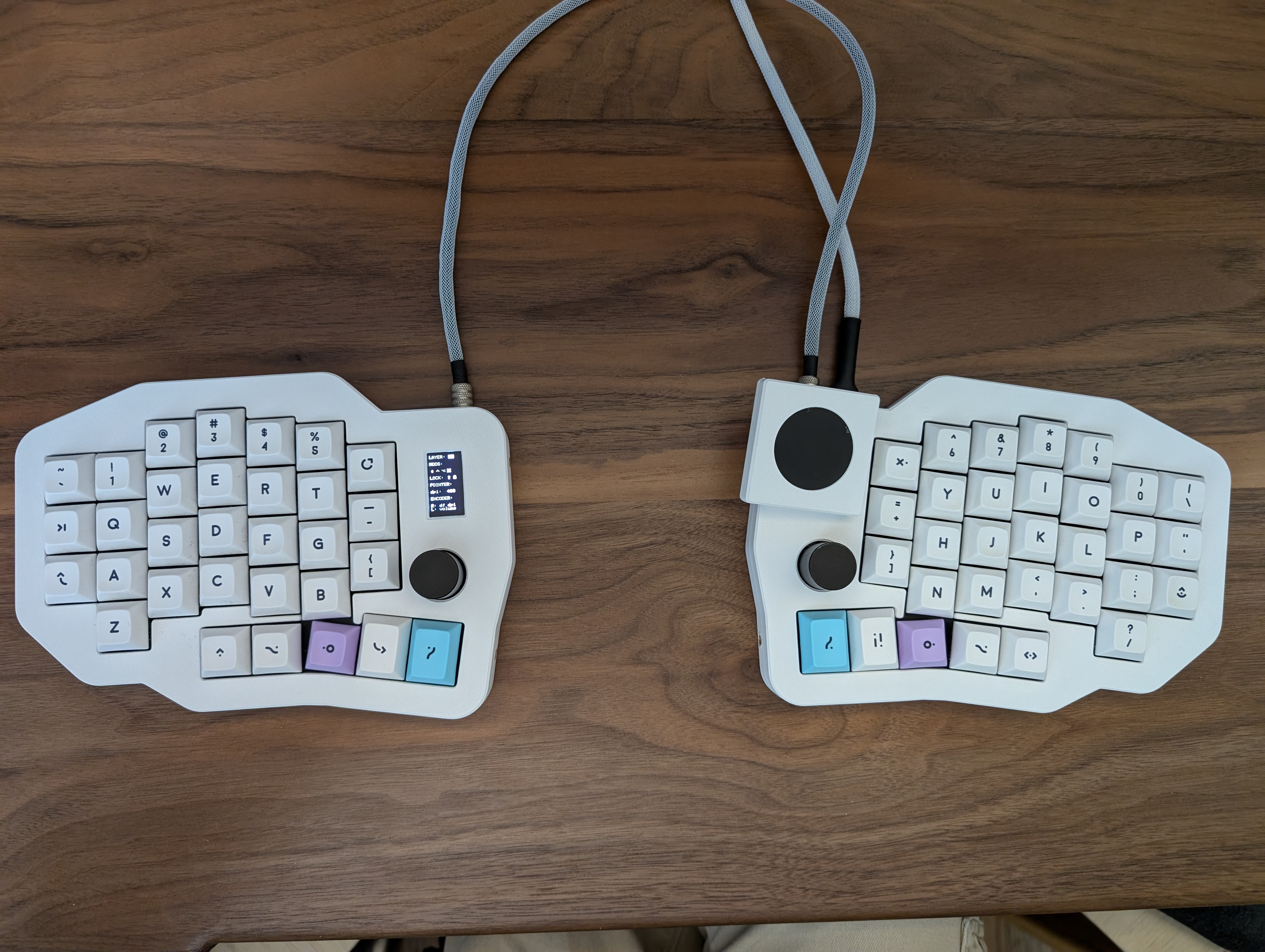
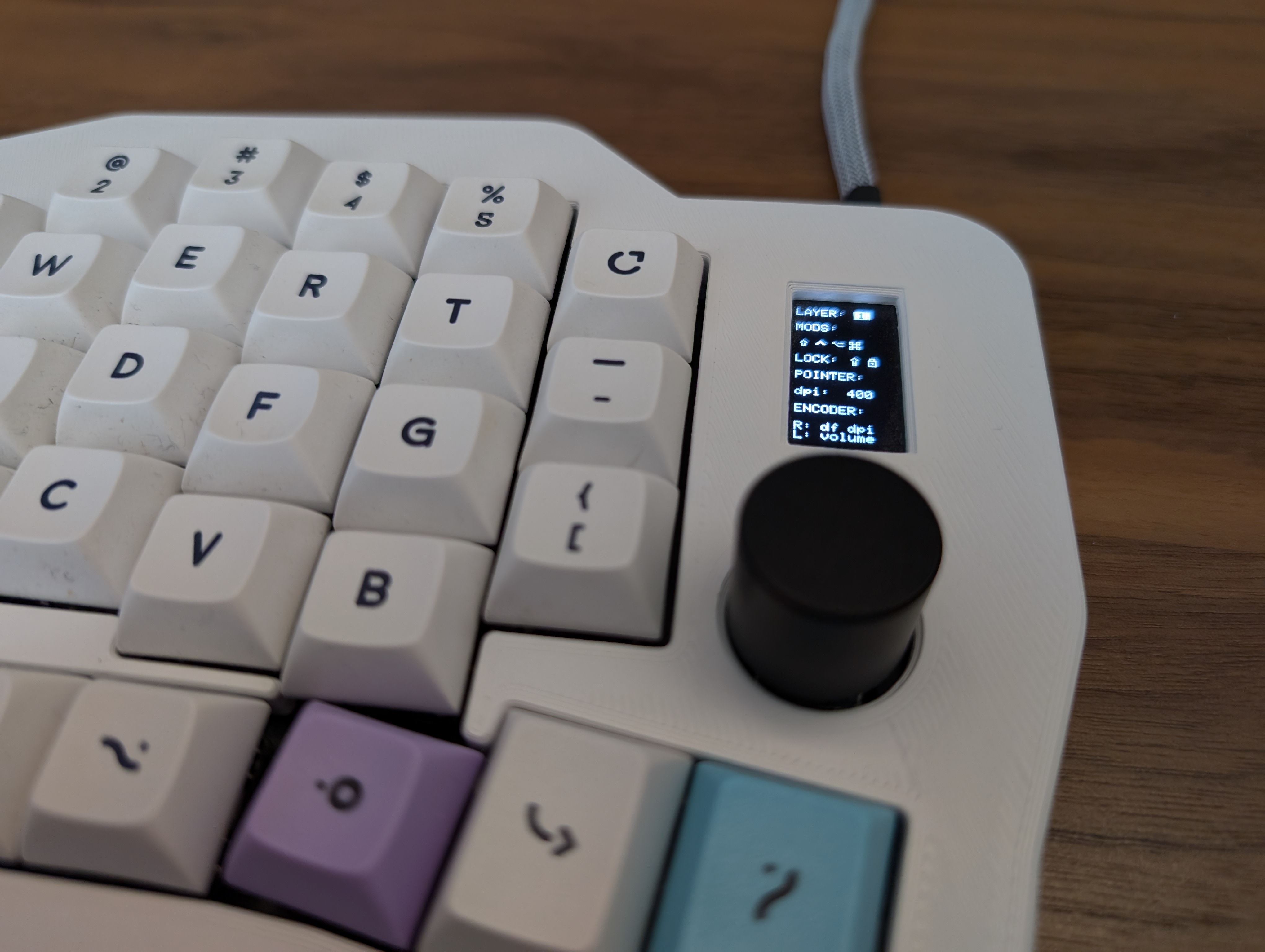
| Left | Right |
|---|---|
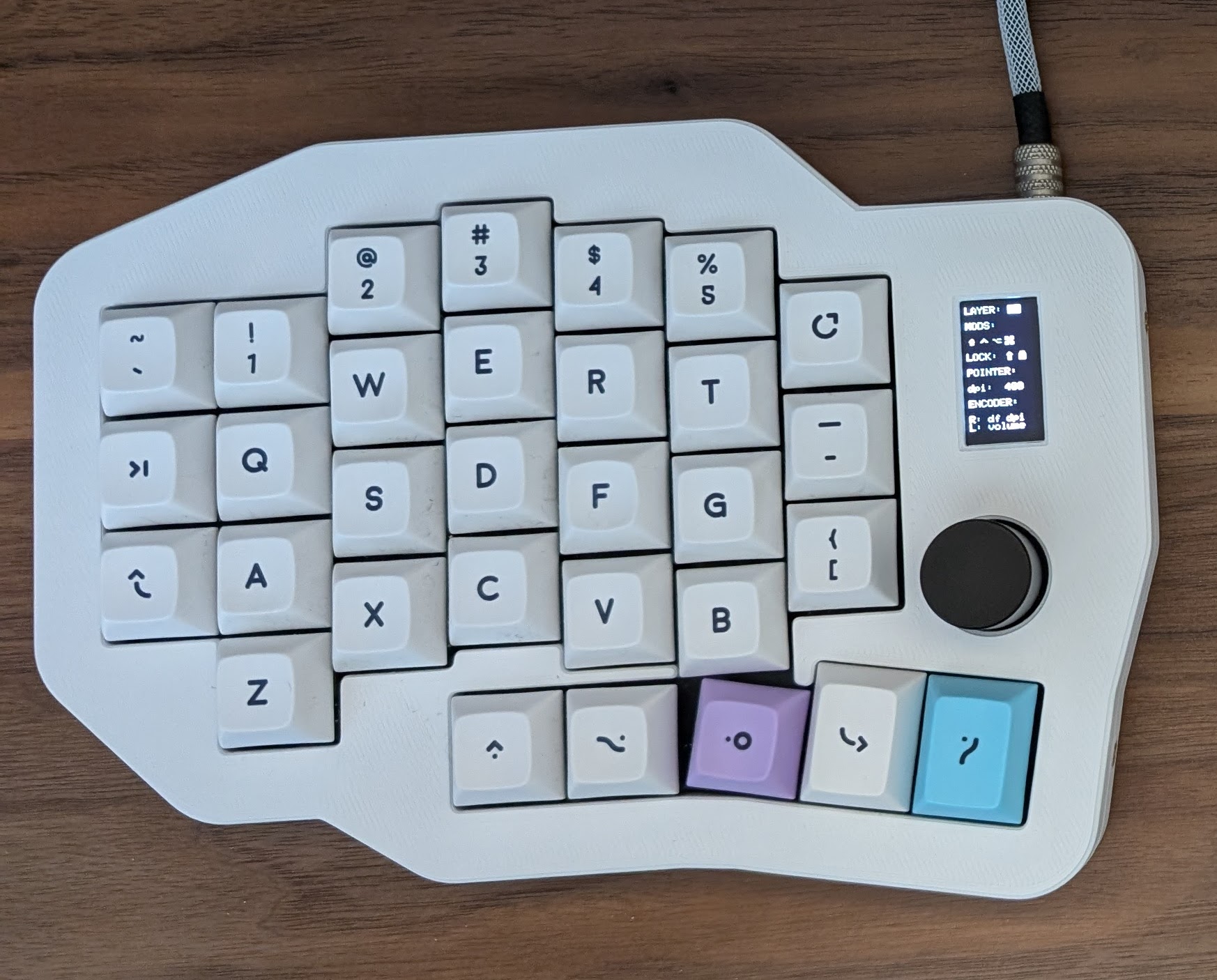 | 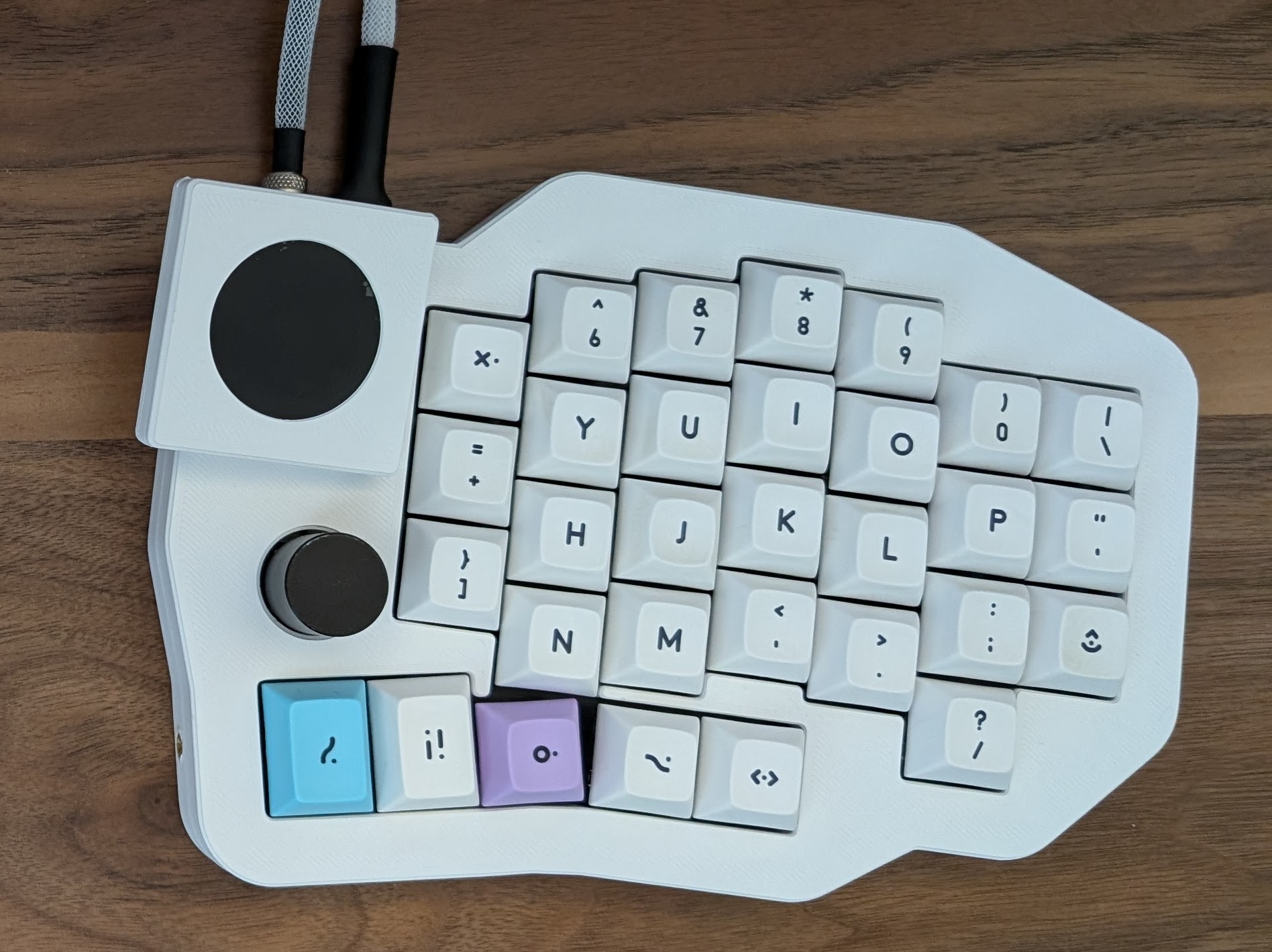 |
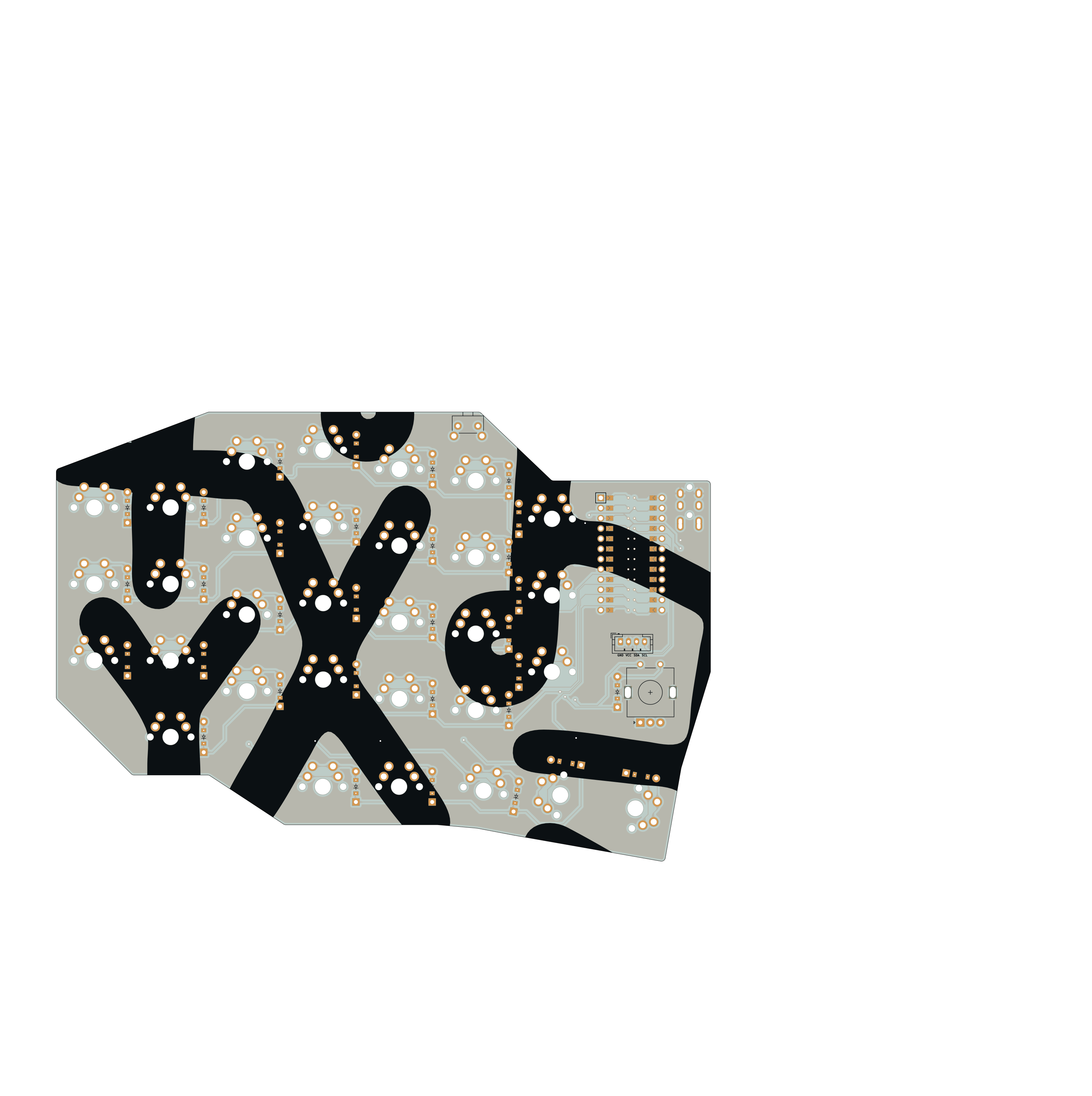 | 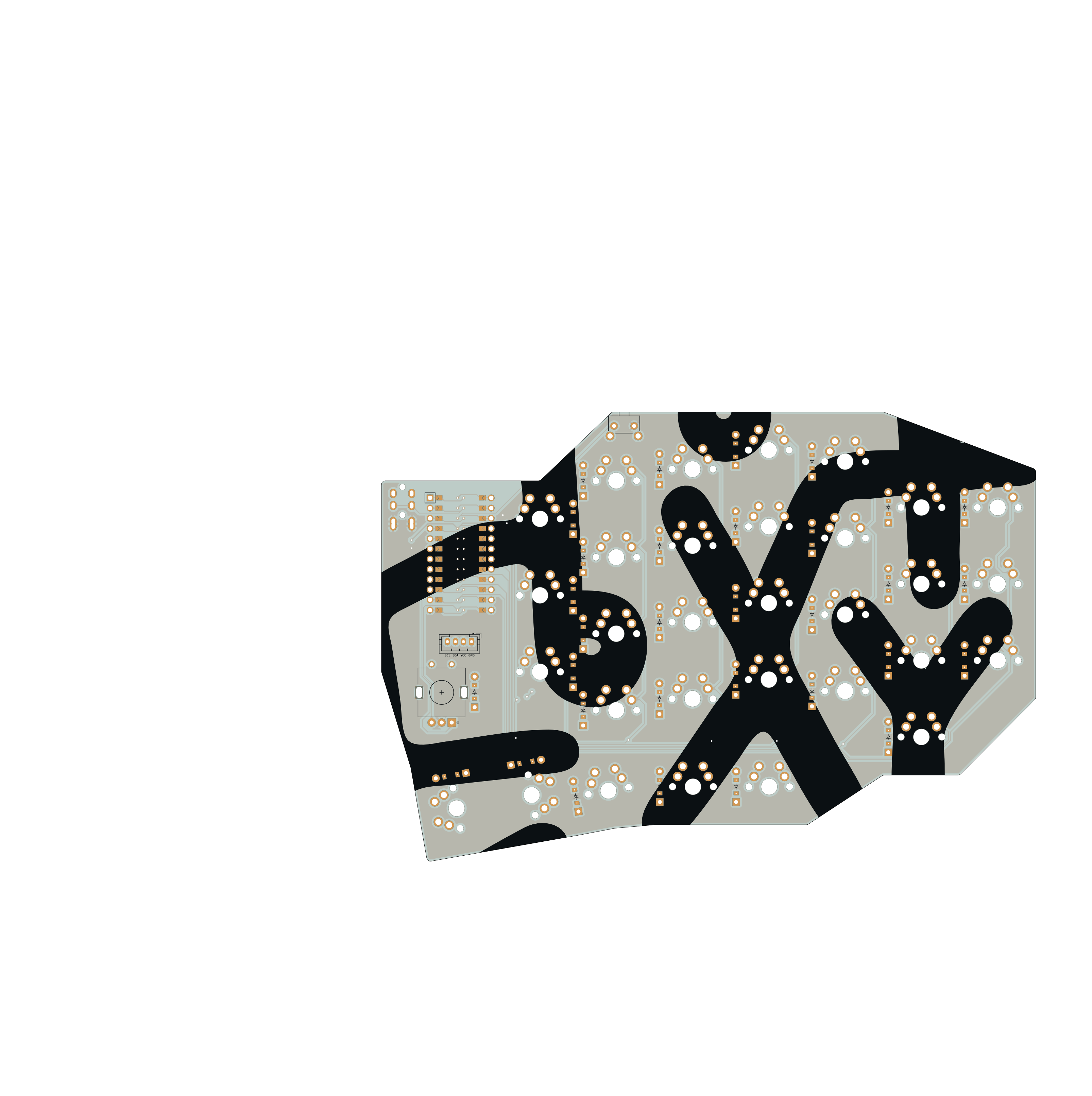 |
I'm not a fan of excessive layers, and many of the popular split keyboards are 3x5 and make heavy use of layers. I used the Ergodash for a while but found the placement of the mods to be uncomfortable, and the top row of the thumb cluster to be unused. Seeing some keyboards (like the bastard keyboards' dilemma) which leveraged the Cirque touchpad inspired me to create my own keyboard which allowed for the layout I wanted, along with all the bells and whistles like rotary encoders, oled screen and touchpad. A secondary purpose of this was to learn Fusion 360, KiCad, and a teensy tiny bit of C and electrical engineering.
| Item | Quantity | Notes |
|---|---|---|
| Spleeb PCB | 2 | |
| Spleeb Plate | 2 | Intended to be cut from FR4 during PCB fab but this can be 3D printed. Extrude the plate dxf to 1.5mm and it will be 3d printable (fit accuracy depends on your printer) |
| Cirque 35mm Touchpad Flat overlay TM035035 | 1 | i2c only. The SPI version can be modified to use i2c. |
| SSD1306 128x64 OLED | 1 | DIYmall model and footprint used in chassis model. Other brands may have fit issues with out modification of the model. |
| Pro Micro pin MCU | 2 | RP2040 recomended. Boardsource Blok used in build |
| MX switches | 62 | |
| 1u keycaps | 58 | |
| 1.25u keycaps | 4 | |
| EC11 Encoder | 2 | Alps Alpine EC11N1524402 used in build |
| Encoder Kob | 2 | 18mm diameter |
| 1N4148 Through Hole Diodes | 64 | SMD diodes supported on PCB but this has not been tested |
| PJ-320A 3.5 mm jack | 2 | |
| Alps Alpine SKHLLCA010 | 2 | Reset Switch |
| JST PH 2.0 mm 4 pin straight connector | 2 | These are optional. Wires can be soldered directly to the though hole pads on the PCB. The connectors make disassembly easier. |
| Mill-Max 315-93 Low Profile Sockets | 48 | These are optional. However the height of regular headers is slightly higher than these, so may need adjusting to the USB cutout |
| Mill-Max 3320 Socket Pins | 48 | These are optional. These are for the Mill-Max sockets |
| Mill-Max 3305-1 Switch Sockets | 124 | These are optional. These allow switches to be swapped with out resoldering |
| M3 M3x5x4 threaded heat set inserts | 8 | Used to fasten bottom to top of chassis. (Same as the Voron 2.4/Trident BOM) |
| M3 12mm length socket head screws | 8 | Used to fasten bottom to top of chassis. 10mm should work as well. |
| M2 4mm installed length threaded heat set inserts | 10 | Used to fasten plate to top and Cirque bracket to top. Up to 20 may be used depending on how much stiffness in the plate is desired. |
| M2 8mm length ultra low profile screws | 8 | Used to attach plate to top. Minimum 8. Up to 20 may be used depending on how many M2 heat set inserts are installed top top. |
| Silicone O-Rings, 4mm OD 1mm ID 1.5mm Width | 16 | Used for a poor man's burger mount isolation for the plate and top |
| M2 4mm length ultra low profile screws | 6 | 2-4 for the oled, 2 for the angled Ciruqe bracket |
| Hookup Wire | x | Needed for OLED and Cirque Touchpad |
Most of this build is straight forward and would follow any PCB build. Look for the diode silkscreen to know which direction didoes should go.
The original chassis CAD files created using Fusion 360 are included and the step files for all parts included as well.
There are more photos not shown in the readme in th images directory.
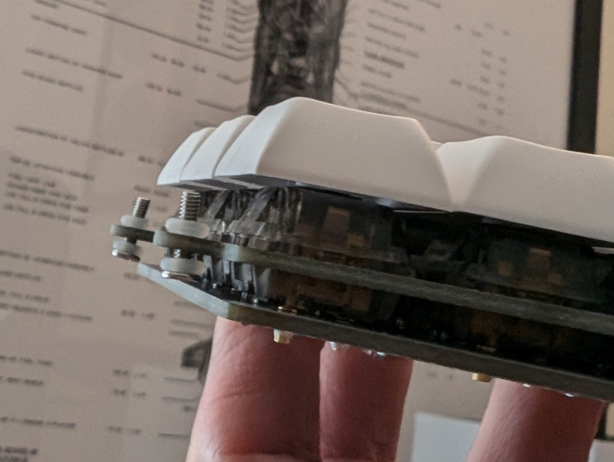
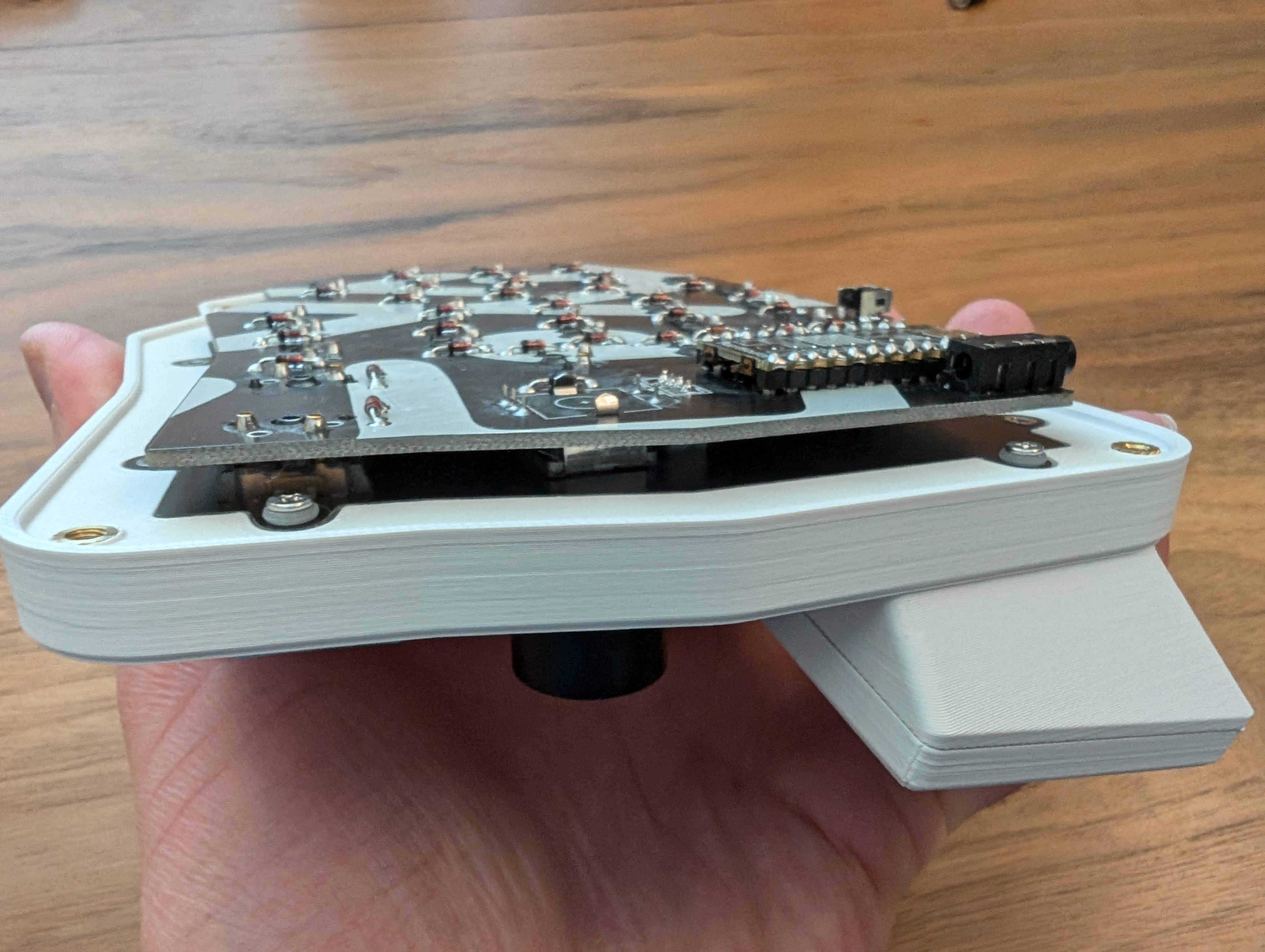
Two silicone O-rings are to be placed in-between the plate and the contact points. One under the screw head and one under the plate. The plate is then screwed into the "top" of the chassis for a top mount approach.
The original plate had 10 attachment points for the "sandwich" mount chassis that was designed before this current iteration. In hindsight this was far too many. While the design and 3d models still support all 10 attachment points, only 4 need to be used.
I am currently using the two on each side of the plate and it feels just fine and there is no rattle. Tightening down the screws all the way is not necessary, just enough so that the plate doesn't move.
 |  |
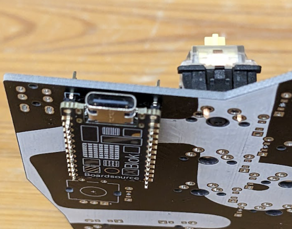
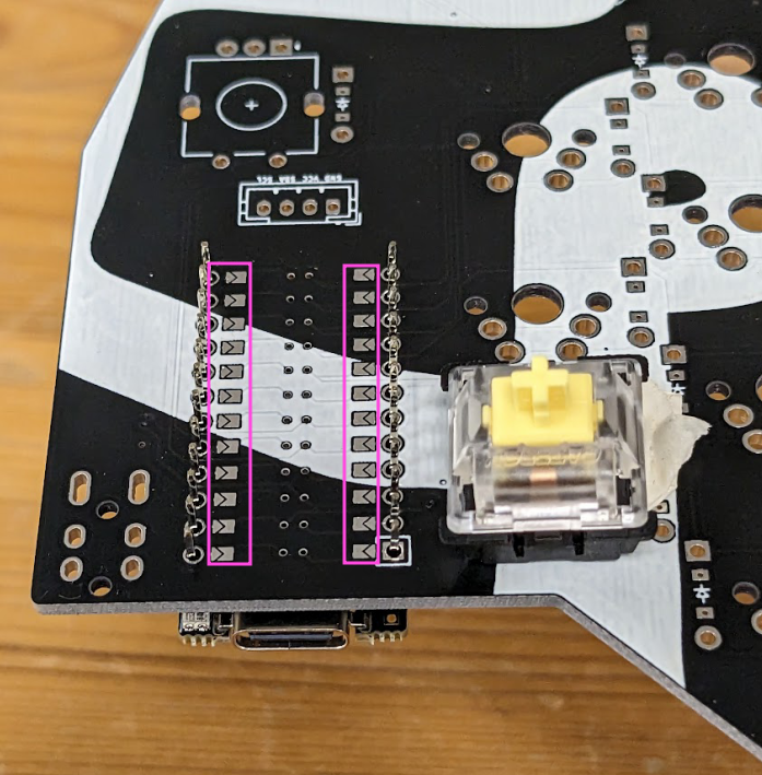
This PCB has solder pads on each side of the PCB. These solder pads allow the MCU to be mounted on either side of the PCB - however the intended use for this build is mounting the MCUs on the underside of the PCB - the side opposite the switches, with the MCU LED facing up. With this orientation the solder pads should be solder on the *same side as the switches.
The solder pad opposite the through hole pad marked with the square 🔳 is RAW.
If you mount the MCU with the LED facing out on the top (same side as switches) you would solder the pads on the top.
If you mount the MCU with the LED facing out on the bottom (opposite side of switches) you would solder the pads on the bottom.
If you mount the MCU with the LED facing in on the top (same side as switches) you would solder the pads on the bottom.
If you mount the MCU with the LED facing in on the bottom (opposite side of switches) you would solder the pads on the top.
Again - with the chassis as designed the last mounting option is the only one supported:
Mount the MCU on the opposite side of the switches, with the LED facing in. Solder the pads on the same side as the switches.
| MCU Orientation | Solder pads on top |
|---|---|
 |  |
Since the PCB is reversible you would mirror this on the other side.
Use hookup wire to solder to the GND, VCC, SDA, SCL pads, and remove the R1 resistor if the SPI version was purchased.
Wires should be hooked up to connector from the "outside" edge of the pcb to "inside" (PCB is reversible)
The bracket is split into three parts.
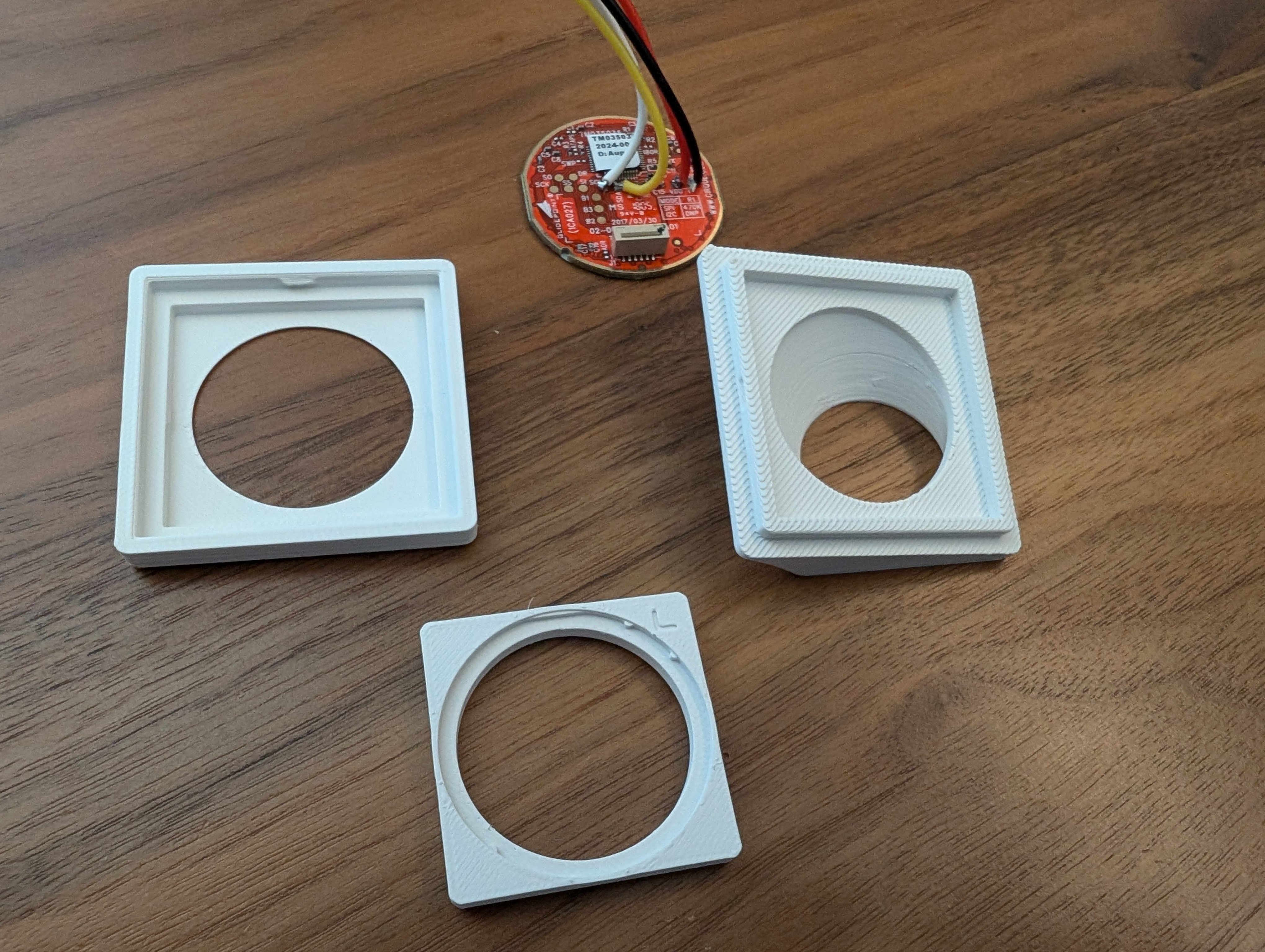 | 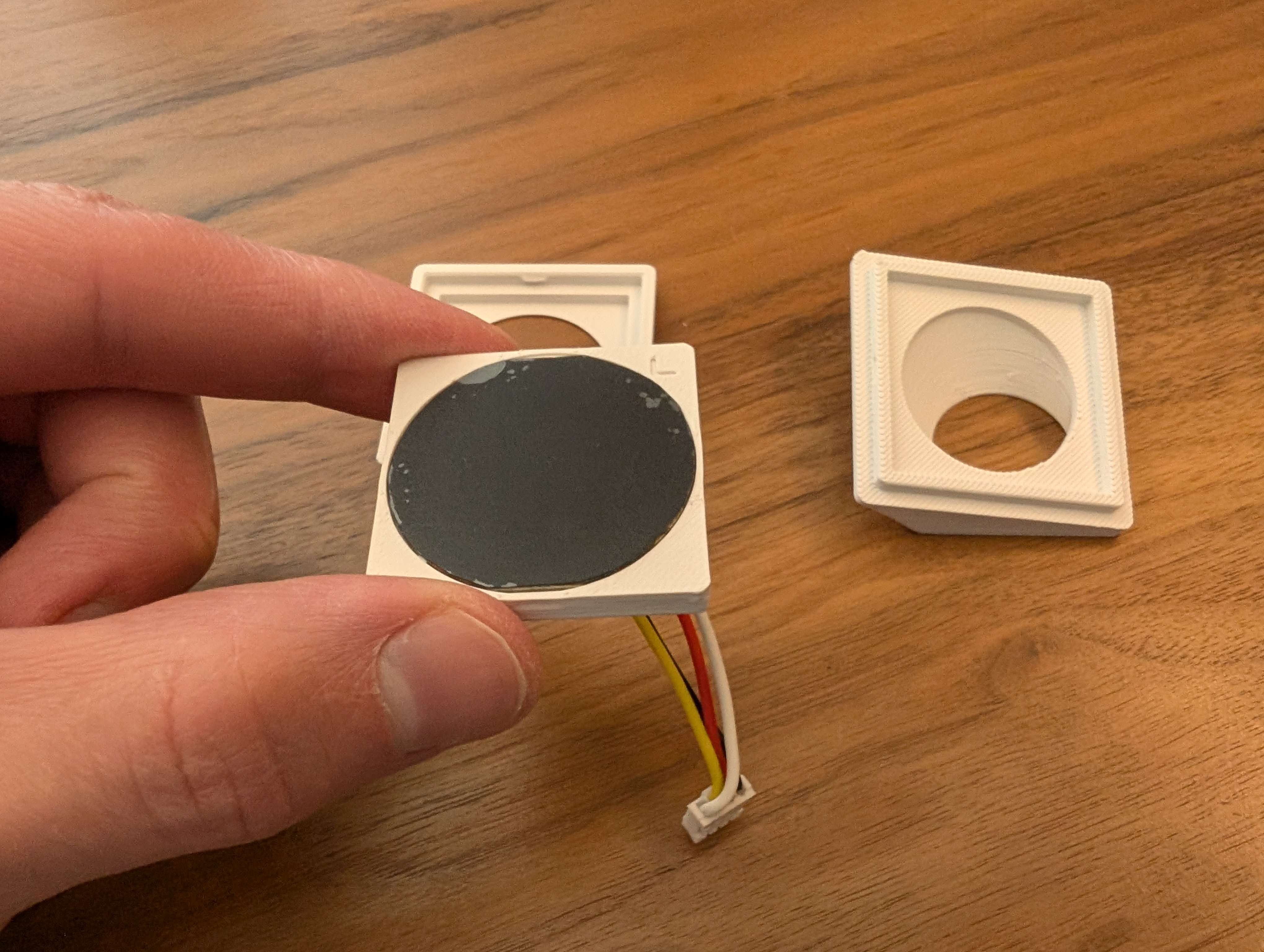 |
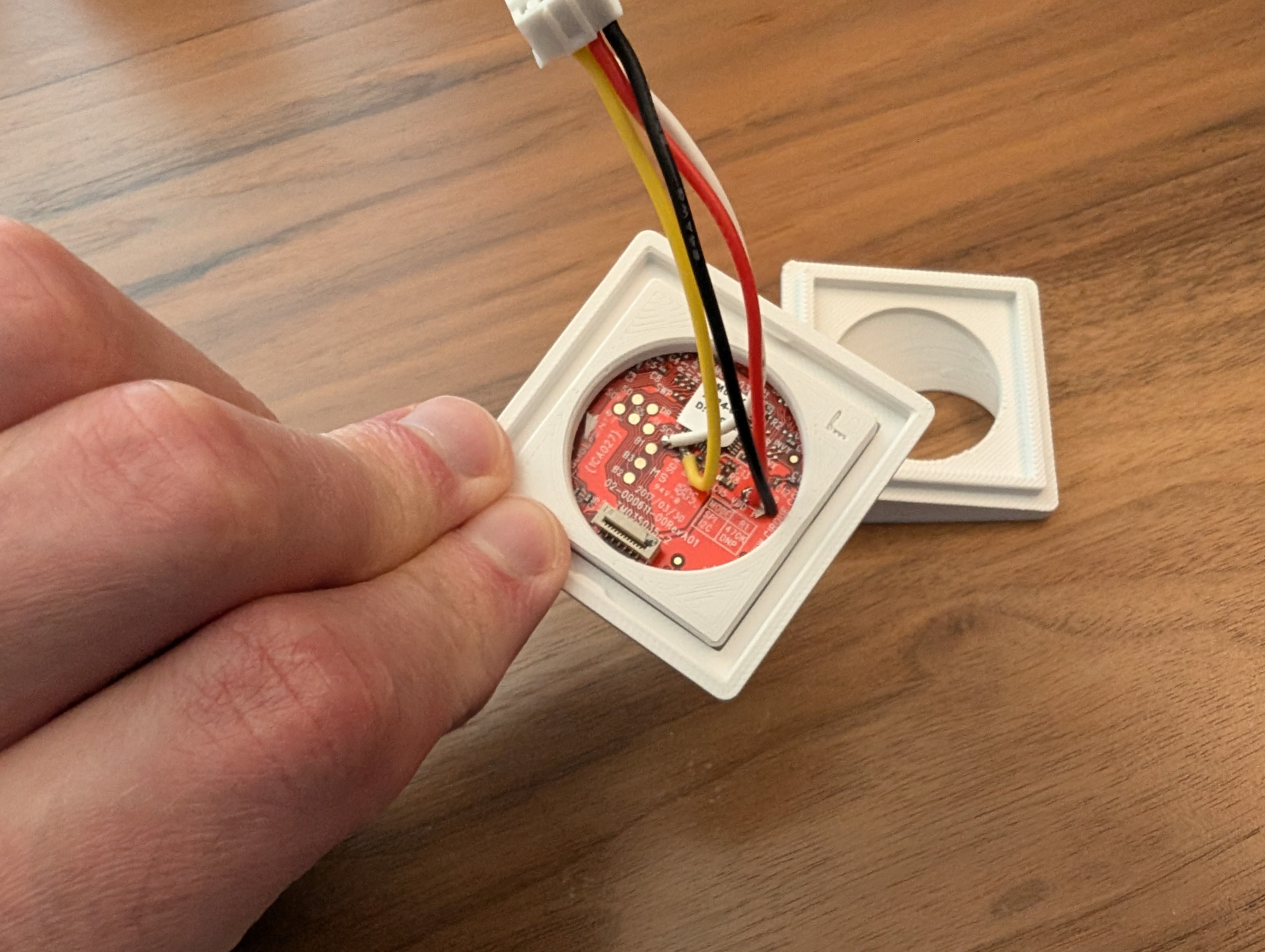 | 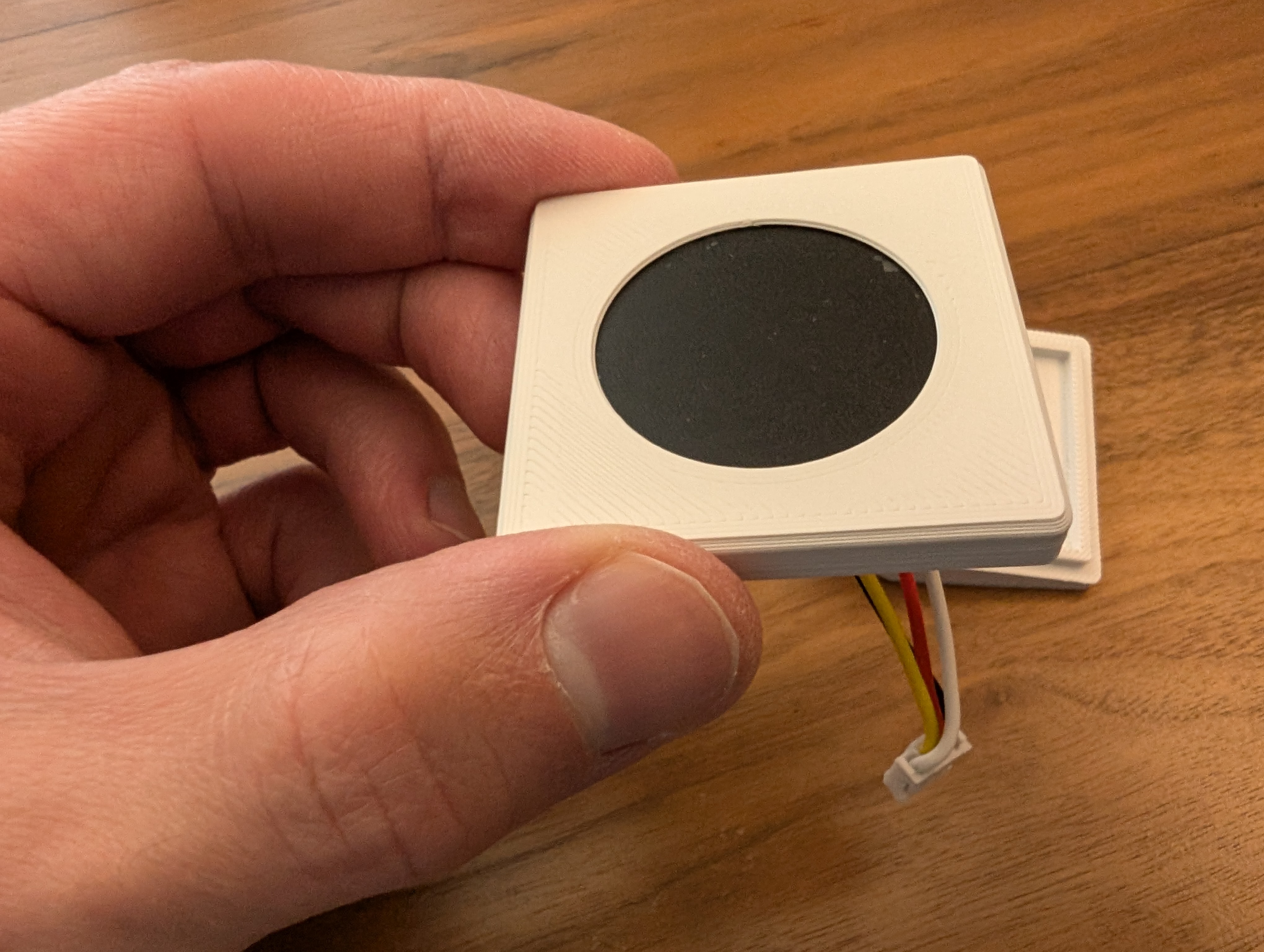 |
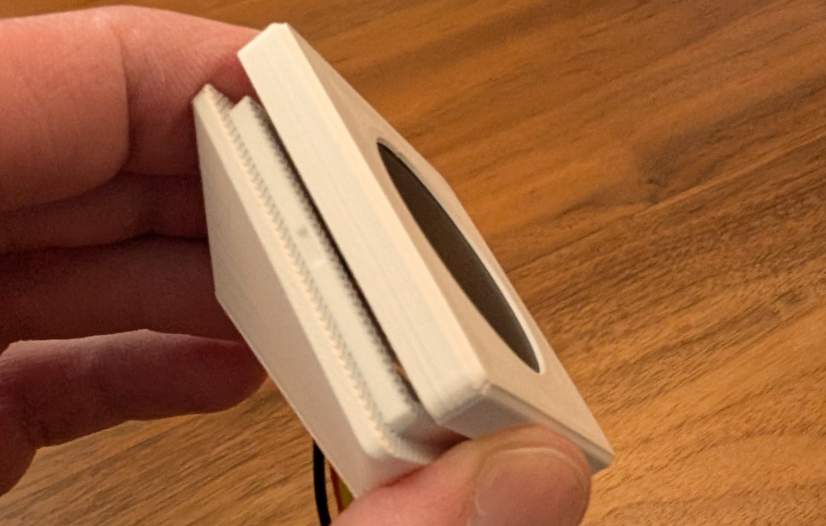 | 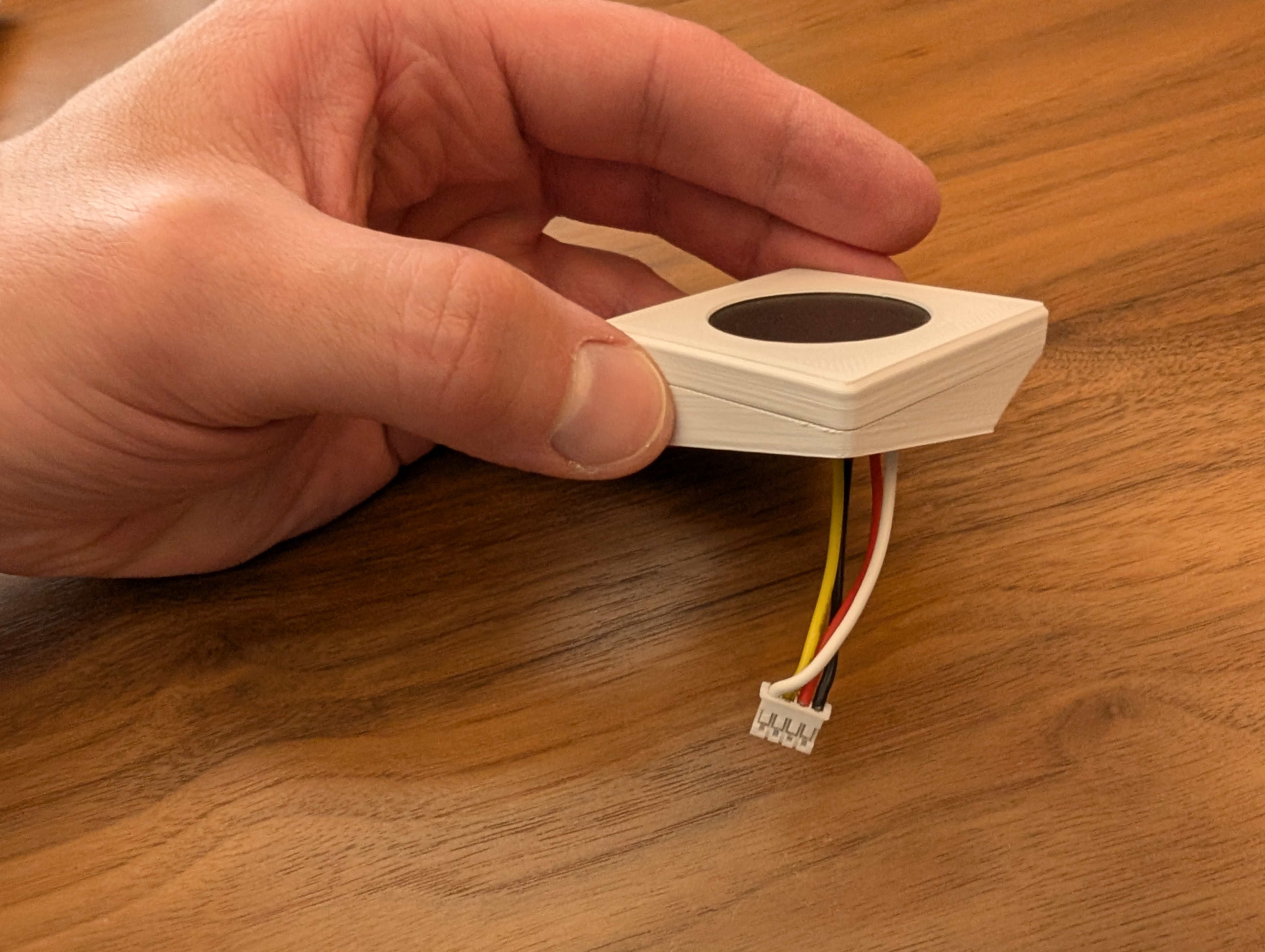 |
The intent is that the 4mm ultra low profile screws should fasten directly into the plastic.
I used ASA but anything should work depending on your printer. I didn't use supports for the 3.5mm and USB cutouts. YMMV on needing supports, but I designed the model to be printed with out supports.
There are features in this model which demand a 0.4 nozzle and 0.2mm layer hight. All other printing parameters are to taste.
Firmware is QMK based and can be found in the QMK GitHub repo.
My personal keymap customizations can be found my my QMK Userspace Fork
| Qty | Value | Footprint | References |
|---|---|---|---|
| 32 | ComboDiode | D1, D2, D10, D11, D12, D13, D14, D15, D16, D17, D18, D19, D20, D21, D22, D23 +16 | |
| 31 | MX | S1, S2, S10, S11, S12, S13, S14, S15, S16, S17, S18, S19, S20, S21, S22, S23 +15 | |
| 1 | svg2mod | Graphic1 | |
| 1 | ProMicro | MCU1 | |
| 1 | JST_PH_S2B-PH-K_02x2.00mm_Angled | JST1 | |
| 1 | rotary_encoder | ROT1 | |
| 1 | SW_SKHLLCA010 | B1 | |
| 1 | TRRS-PJ-320A-dual | TRRS-PJ-320A-dual | TRRS1 |
It measures 163.1 × 111.9 mm and has 2 copper layers, 1.6 mm thick.
69 parts. The full list of its parts is on this page, with links to each part's symbol and footprint where PCBKit's library has them.
From the chrishoage/spleeb repository on GitHub, at the commit this page was made from: the board is spleeb/pcbs/spleeb.kicad_pcb. PCBKit opens the board in the browser, with nothing to install.
Its repository publishes it under the MIT licence: you may reuse it on that licence's terms (keep the author's notice, and for a copyleft licence share your changes alike).

jackw01/scanlight
A better light source for scanning color negative film

Biacco42/Ergo42
7x4 ortho linear split keyboard - The Answer to the Ultimate Question of Life, the Universe, and at least Keyboards

eigenco/frankenpi
This is an experimental project to connect Raspberry Pi with the help of cheap Cyclone IV FPGA board to 8-bit ISA bus to act as multiple different devices.

mattybrad/drumkid
Version 4 was the first successful working design, with full code, schematics, Gerbers, etc available on GitHub.

KaiPereira/Overglade-Badges
NFC hackathon badges for the Overglade game jam in Singapore!

BerkeleyHCI/PolymorphicBlocks
A Python-based hardware description language for PCBs for higher-level (block-diagram / system-architecture level) PCB design through libraries of directly reusable subcircuit generators.
