4 layers69.9 × 44.5 mm
DoughLee2
chl33/Dough133
A temperature-controlled container for proofing and fermenting soughdough
62 parts3MIT

 chl33/LoRa1331
A base station for LoRa-based satellite sensor devices.
LoRa133 is an open-source printed circuit board by chl33, from the chl33/LoRa133 repository on GitHub, published under the MIT licence. It is a 4-layer board of 49.5 × 39.4 mm with 22 parts on 50 nets, routed with 217 tracks and 62 vias.
It is built around the ESP32-WROOM-32, SHTC3 and AMS1117-3.3, with the RFM95W-915S2 and SS14 among its other parts. Its parts include 4 ICs, 2 connectors, 1 diode and 1 fuse. It belongs with the radio and wireless and home automation and IoT boards and the ESP32 boards of this library.


This project is a base station for LoRa-based satellite sensor devices such as Garden133. It includes KiCAD board design and C++ firmware. LoRa133 allows satellite sensor units to communicate using LoRa radio modules and automatically integrate with Home Assistant. I build the firmware using the Platformio build system.
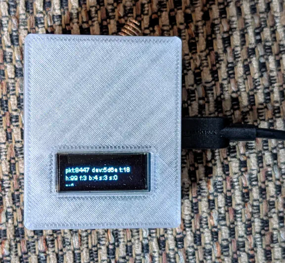
This is a picture of the base station in its project box in OpenSCAD/Lora133/.
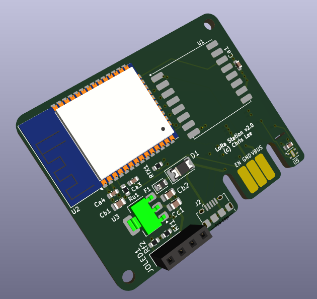
This is the PCBA documented in KiCAD/LoRa133/.
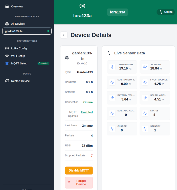
Here is what the web interface (written in Svelte) looks like:
Please see the Introducing Garden133 blog post for more information.
This device uses these libraries:
| Qty | Value | Footprint | References |
|---|---|---|---|
| 4 | 100nF | Capacitor_SMD:C_0603_1608Metric | Ca1, Ca2, Ca3, Ca4 |
| 2 | 2.2k | Resistor_SMD:R_0603_1608Metric | Rf1, Rf2 |
| 1 | 0.5A | Diode_SMD:D_0805_2012Metric | F1 |
| 1 | 10k | Resistor_SMD:R_0603_1608Metric | Ru1 |
| 1 | 10uF | Capacitor_SMD:C_0805_2012Metric_Pad1.18x1.45mm_HandSolder | Cb2 |
| 1 | 10uF | Capacitor_SMD:C_0805_2012Metric | Cb1 |
| 1 | 470 | Resistor_SMD:R_0603_1608Metric | RTX1 |
| 1 | 47uF | Capacitor_SMD:C_0805_2012Metric_Pad1.18x1.45mm_HandSolder | Cc1 |
| 1 | AMS1117-3.3 | Package_TO_SOT_SMD:SOT-223-3_TabPin2 | U3 |
| 1 | Conn_01x04_Socket | Connector_PinSocket_2.54mm:PinSocket_1x04_P2.54mm_Vertical | JOLED1 |
| 1 | ESP32-WROOM-32 | RF_Module:ESP32-WROOM-32 | U2 |
| 1 | Edge2x6_Connector | chl33_library:EdgeConnector_2x3 | J3 |
| 1 | RFM95W-915S2 | RF_Module:HOPERF_RFM9XW_SMD | U1 |
| 1 | SHTC3 | Sensor_Humidity:Sensirion_DFN-4-1EP_2x2mm_P1mm_EP0.7x1.6mm | U5 |
| 1 | SS14 | Diode_SMD:D_2010_5025Metric | D1 |
| 1 | USB_B_Micro | Connector_USB:USB_Micro-B_Amphenol_10118194_Horizontal | J2 |
The 20 most common of 22 parts.
chl33/Dough133
A temperature-controlled container for proofing and fermenting soughdough


chl33/Plant133
Firmware, circuit design, and 3D-printable components for an automated plant-watering system.


kokhaie/Smart-Refrigerator-Demo
The KiCad-generated BOM is mirrored into the documentation site under docs/ so it can be published through GitHub Pages.

nuclearcat/ESP32ETH
Simple ESP32 with native ethernet using LAN8720 phy, Arduino compatible

epim/circsim
Post-routed PCB+Schematic circuit simulator. Because I have trust issues.

PhilipHiet/ESP32-RTL8201F-devboard
Develpoment-board for the ESP32 with a RTL8201F ethernet transceiver and an onboard USB-C debug-interface
It measures 49.5 × 39.4 mm and has 4 copper layers, 2.07 mm thick.
22 parts, built around the ESP32-WROOM-32, SHTC3, AMS1117-3.3 and RFM95W-915S2. The full list of its parts is on this page, with links to each part's symbol and footprint where PCBKit's library has them.
From the chl33/LoRa133 repository on GitHub, at the commit this page was made from: the board is KiCAD/LoRa133/LoRa133.kicad_pcb and its schematic KiCAD/LoRa133/LoRa133.kicad_sch. PCBKit opens the board in the browser, with nothing to install.
Its repository publishes it under the MIT licence: you may reuse it on that licence's terms (keep the author's notice, and for a copyleft licence share your changes alike).