4 layers49.5 × 39.4 mm

 chl33/Dough1333
A temperature-controlled container for proofing and fermenting soughdough
DoughLee2 is an open-source printed circuit board by chl33, from the chl33/Dough133 repository on GitHub, published under the MIT licence. It is a 4-layer board of 69.9 × 44.5 mm with 62 parts on 61 nets, routed with 462 tracks and 77 vias.
It is built around the ESP32-WROOM-32, SHTC3 and BD90610EFJ-CE2, with the 74LVC1G08Z, AMS1117-3.3 and SN74LVC1G123DCUR among its other parts. Its parts include 5 ICs, 2 connectors, 1 capacitor and 1 inductor. It belongs with the ESP32 boards of this library.


Dough133 is a temperature-controlled container for proofing and fermenting sourdough. It uses a small cooler and a PTC heater with a fan to heat the inside of the cooler. A PCBA with an ESP32 controls the power supplied to the heater to regulate the temperature of the enclosure.
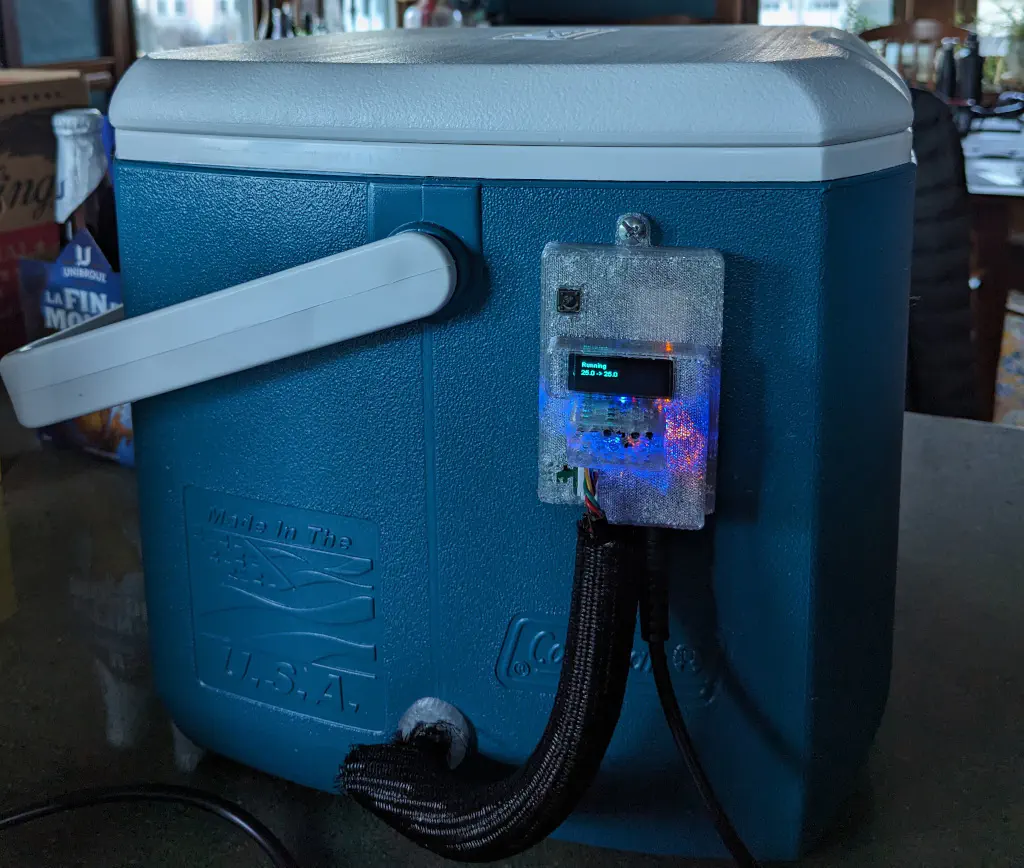
This repository contains:
Instructions for the assembly of the device are in this are at my blog.
Please also see the other entries describing this project:
Components needed for making this device, along with links and approximate price as of September 2024:
| Item | Source | Approximate cost |
|---|---|---|
| Coleman 16 qt cooler | Amazon | $23 |
| PTC Air Heater 12V 100W | AliExpress | $7 |
| DC 12V 5A Power Supply | Amazon | $12 |
The circuit board design is in KiCAD/.
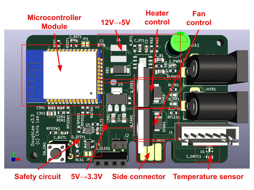
These require footprints in chl33_library and symbols in chl33_kicad_sym.
Designs for 3D-printable components are in scad/.
The EBox is based on the ProjectBox OpenSCAD system.
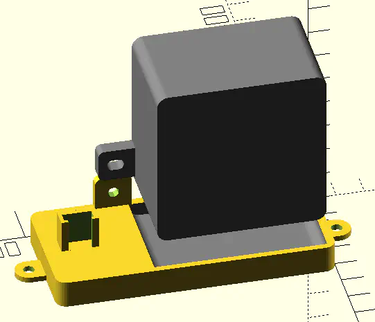
The heater mount secures the heater and temperature/humidity sensor inside the cooler.
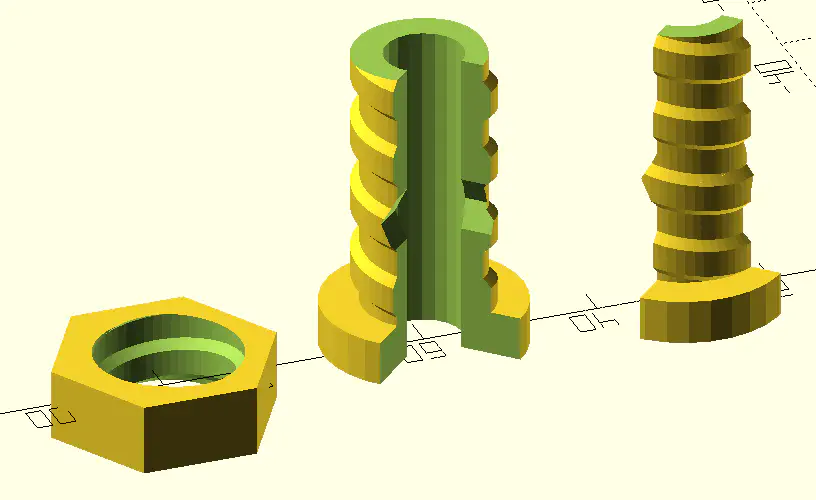
The Cooler plug helps avoid heat leaking through the hole through which wires run from the heater mount through the wall of the cooler to the EBox.
The software is based on the og3 library and built using PlatformIO.
WifiWatchdog recovery, and a software-monitored 200 Hz heartbeat pulse for the hardware safety circuit (SN74LVC1G123) to cut heater power if the main loop or control loop stalls.npm for building the Svelte web interface.The project uses ini files for local configuration and secrets. Create secrets.ini and local.ini based on the provided examples:
Secrets (secrets.ini):
Copy secrets.ini.example to secrets.ini and configure:
[secrets]
otaPassword = my_secure_password ; Password for Over-The-Air updates
Local Build & Upload Settings (local.ini):
Copy local.ini.example to local.ini:
[platformio]
default_envs = wifi              ; Use 'usb' for serial flashing or 'wifi' for OTA

[local]
uploadPort = 192.168.1.100       ; IP address of the board for OTA uploads
build_flags =
    '-D LOG_UDP'
    '-D LOG_UDP_ADDRESS=192, 168, 1, 50'
wifi_upload_flags =cd svelte && npm ci && cd ..default_envs or -e):
pio run -e usb -t upload   # Flash via USB (/dev/ttyUSB0)
pio run -e wifi -t upload # Flash via OTApio device monitorOnce connected to WiFi, navigate to the device's IP address (displayed on the OLED).
Ensure your MQTT broker details are configured in the Web UI. The device will automatically appear in Home Assistant as a climate device (Thermostat) if MQTT discovery is enabled.
| Qty | Value | Footprint | References |
|---|---|---|---|
| 6 | 100nF | Capacitor_SMD:C_0603_1608Metric | C_RST1, Ca1, Ca2, Ca3, Ca4, Ca5 |
| 4 | 1k | Resistor_SMD:R_0603_1608Metric | Rl1, Rl2, Rl3, Rl4 |
| 3 | LED | LED_SMD:LED_0603_1608Metric | D_HR1, D_LFN1, D_SFTY1 |
| 2 | 100k | Resistor_SMD:R_0603_1608Metric | R_T1, RPUSW1 |
| 2 | 10k | Resistor_SMD:R_0603_1608Metric | Ru3, Ru4 |
| 2 | 10uF | Capacitor_SMD:C_0805_2012Metric_Pad1.18x1.45mm_HandSolder | Cb2, Cb3 |
| 2 | 12k | Resistor_SMD:R_0603_1608Metric | Ru1, Ru2 |
| 2 | 2.2k | Resistor_SMD:R_0603_1608Metric | Rf1, Rf2 |
| 2 | 470 | Resistor_SMD:R_0603_1608Metric | RRST1, Rt3 |
| 2 | 490 | Resistor_SMD:R_0603_1608Metric | Rt1, Rt2 |
| 2 | Barrel_Jack | Connector_BarrelJack:BarrelJack_Horizontal | JHTR1, JPWR1 |
| 2 | IRLB8721PBF | Package_TO_SOT_THT:TO-220-3_Vertical | Q_FAN1, Q_HTR1 |
| 2 | SolderJumper_2_Open | Jumper:SolderJumper-2_P1.3mm_Open_Pad1.0x1.5mm | JP1, JP2 |
| 1 | 100 μH | chl33_library:CD54 | L1 |
| 1 | 100pF | Capacitor_SMD:C_0603_1608Metric_Pad1.08x0.95mm_HandSolder | C_RT1 |
| 1 | 10nF (50V) | Capacitor_SMD:C_0805_2012Metric_Pad1.18x1.45mm_HandSolder | CB1 |
| 1 | 180pF (50V) | Capacitor_SMD:C_0603_1608Metric | C2 |
| 1 | 1N4001 | Diode_SMD:D_SMB | DFAN1 |
| 1 | 220uF (35Vx2) | Capacitor_THT:CP_Radial_D6.3mm_P2.50mm | Cbulk1 |
| 1 | 27k | Resistor_SMD:R_0603_1608Metric | R_RT1 |
| 1 | 33k | Resistor_SMD:R_0603_1608Metric | RB1 |
| 1 | 4.7uF | Capacitor_SMD:C_0805_2012Metric_Pad1.18x1.45mm_HandSolder | C_B1 |
| 1 | 43k | Resistor_SMD:R_0603_1608Metric | RB2 |
| 1 | 44uF (16V) | Capacitor_SMD:C_0603_1608Metric | Cc2 |
| 1 | 47uF | Capacitor_SMD:C_0805_2012Metric_Pad1.18x1.45mm_HandSolder | Cc1 |
| 1 | 74LVC1G08 | chl33_library:SOT-23-5 | U5 |
| 1 | 8.2k | Resistor_SMD:R_0603_1608Metric | RB3 |
| 1 | AMS1117-3.3 | Package_TO_SOT_SMD:SOT-223-3_TabPin2 | U3 |
| 1 | BD90610EFJ-CE2 | chl33_library:BD90610EFJ-CE2 | U_B1 |
| 1 | BLU | LED_SMD:LED_0603_1608Metric | D_PWR1 |
| 1 | Conn_01x04_Female | Connector_PinSocket_2.54mm:PinSocket_1x04_P2.54mm_Vertical | J_OLED1 |
| 1 | Conn_01x06 | Connector_JST:JST_XH_B6B-XH-A_1x06_P2.50mm_Vertical | J1 |
| 1 | ESP32-WROOM-32 | RF_Module:ESP32-WROOM-32 | U2 |
| 1 | Edge2x6_Connector | chl33_library:EdgeConnector_2x3 | J3 |
| 1 | SHTC3 | Sensor_Humidity:Sensirion_DFN-4-1EP_2x2mm_P1mm_EP0.7x1.6mm | U1 |
| 1 | SN74LVC1G123DCUR | chl33_library:SOP50P310X90-8N | U4 |
| 1 | SS34 | Diode_SMD:D_SMA | DB1 |
| 1 | SS34-E3/9AT | Diode_SMD:D_SMB | DHR1 |
| 1 | SW_Push | Button_Switch_THT:SW_PUSH_6mm | SW_ON1 |
The 59 most common of 62 parts.
It measures 69.9 × 44.5 mm and has 4 copper layers, 2.07 mm thick.
62 parts, built around the ESP32-WROOM-32, SHTC3, BD90610EFJ-CE2 and 74LVC1G08Z. The full list of its parts is on this page, with links to each part's symbol and footprint where PCBKit's library has them.
From the chl33/Dough133 repository on GitHub, at the commit this page was made from: the board is KiCAD/DoughLee2.kicad_pcb and its schematic KiCAD/DoughLee2.kicad_sch. PCBKit opens the board in the browser, with nothing to install.
Its repository publishes it under the MIT licence: you may reuse it on that licence's terms (keep the author's notice, and for a copyleft licence share your changes alike).


0x616c6f6e/esp32s31-mp3
打开 q2-v2.kicadpro。这是 ESP32-S31NRV16 裸芯片版的独立工程,当前按用户要求改为 0402 阻容、电源分区铺铜并就近打过孔,信号待手动布线。不是可打板文件。原生产主板 hardware-q2 的 PCB 保持原文件哈希。

manvalan/MuonScope
Piano di rivelazione MuonScope con 16 fotodiodi VBPW34S in matrice 4×4 a passo 10 mm, per il bus MIKILAB REV5.1.

Matthew-Garcia/NASA-Lunabotics-UHCL-Lunar-Hawks
UHCL Lunar Hawks proof-of-concept excavation rover: ROS 2, micro-ROS, MicroPython, control PCB development, CAD, and research.

RyanHailey21/neuromorphic-IR-hand-assembled
All through-hole re-implementation of the Rev A neuromorphic IR event sensor: no SMD parts, solderable with a basic iron.

sbarisic/MagMouse
Open source hall-effect based mouse - no mechanical contacts - no failure points
