2 layers60 × 30 mm
Controller
google/mozc-devices
Circuit diagrams and firmware source code for Gboard DIY keyboards
11 parts3kApache-2.0
 chdabre/race-timer
A race timing system built with an ESP32-S3 microcontroller and LED display that measures elapsed time between start and finish sensors.
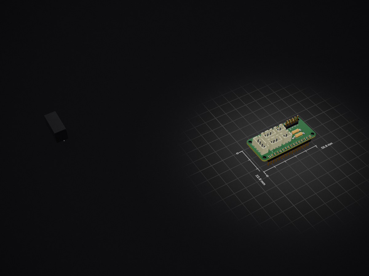
Race timer feather is an open-source printed circuit board by chdabre, from the chdabre/race-timer repository on GitHub, published under the CC-BY-SA-4.0 licence. It is a 2-layer board of 50.8 × 22.9 mm with 11 parts on 32 nets, routed with 67 tracks and 4 vias.
Its parts include 8 connectors and 2 resistors. It belongs with the microcontroller boards boards of this library.

A race timing system built with an ESP32-S3 microcontroller and LED display that measures elapsed time between start and finish sensors.
The connection box can provide power to multiple timer modules, and provides a reset button to reset all modules at once.
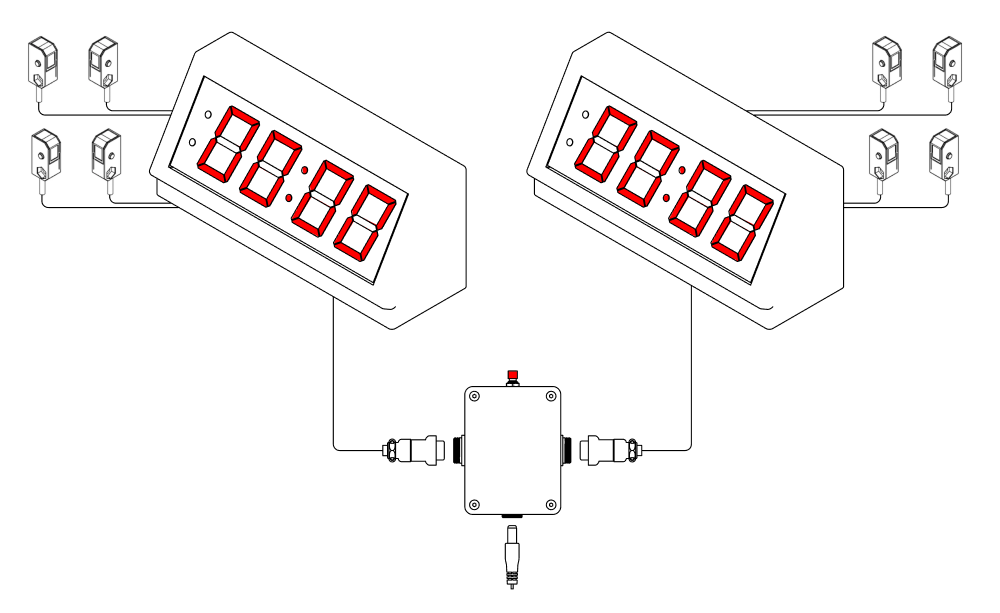
The system is designed to be easy to use and assemble. The timer modules are designed to be mounted to a table, and all wiring is run underneath the table.
The timer modules are connected to the connection box with a removable connector, so each module can be transported individually.
If more than 2 modules are needed, the connection box can be easily extended with additional connectors.
Two light barriers are connected to each timer module, each consisting of a transmitter and receiver.
The START barrier is mounted at the beginning of the race track. The STOP barrier is mounted at the end of the race track.
When the START barrier is interrupted, the current time measurement is reset and a new timing begins.
When the STOP barrier is interrupted while timing is active, the timing stops and the final time is shown on the display.
If a timing measurement exceeds 100 seconds, the time can no longer be fully displayed. The seconds display resets to 00: and timing continues.
When the RESET button is pressed at any time, the current timing is stopped and the display immediately resets to 00:00.
The firmware is developed using the Arduino Platform on PlatformIO. The project is configured for the Adafruit ESP32-S3 Feather board.
The following libraries are required and will be automatically installed by PlatformIO:
The serial monitor can be opened at 115200 baud to view debug messages.
See also the KiCad project in the hardware folder.
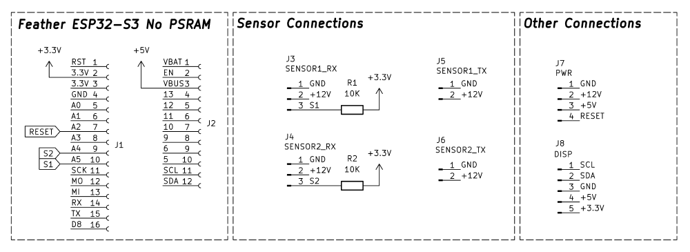
FeatherWing Schematic
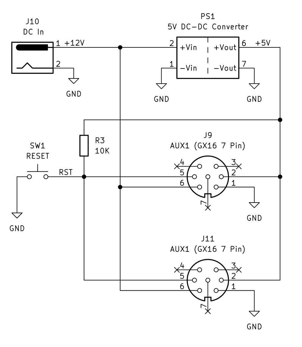
Connection Box Schematic
Per Timer Module
Connection Box
This work is licensed under a Creative Commons Attribution-ShareAlike 4.0 International License.

| Qty | Value | Footprint | References |
|---|---|---|---|
| 2 | 10K | Resistor_THT:R_Axial_DIN0207_L6.3mm_D2.5mm_P10.16mm_Horizontal | R1, R2 |
| 1 | 5V DC-DC Converter | Converter_DCDC:Converter_DCDC_XP_POWER-ITXxxxxSA_THT | PS1 |
| 1 | DISP | Connector_PinHeader_2.54mm:PinHeader_1x05_P2.54mm_Vertical | J8 |
| 1 | PWR | Connector_JST:JST_XH_B4B-XH-A_1x04_P2.50mm_Vertical | J7 |
| 1 | SENSOR1_RX | Connector_JST:JST_XH_B3B-XH-A_1x03_P2.50mm_Vertical | J3 |
| 1 | SENSOR1_TX | Connector_JST:JST_XH_B2B-XH-A_1x02_P2.50mm_Vertical | J5 |
| 1 | SENSOR2_RX | Connector_JST:JST_XH_B3B-XH-A_1x03_P2.50mm_Vertical | J4 |
| 1 | SENSOR2_TX | Connector_JST:JST_XH_B2B-XH-A_1x02_P2.50mm_Vertical | J6 |
| 1 | ~ | Connector_PinSocket_2.54mm:PinSocket_1x12_P2.54mm_Vertical | J2 |
| 1 | ~ | Connector_PinSocket_2.54mm:PinSocket_1x16_P2.54mm_Vertical | J1 |
It measures 50.8 × 22.9 mm and has 2 copper layers, 1.6 mm thick.
11 parts. The full list of its parts is on this page, with links to each part's symbol and footprint where PCBKit's library has them.
From the chdabre/race-timer repository on GitHub, at the commit this page was made from: the board is hardware/race-timer_feather/race-timer_feather.kicad_pcb and its schematic hardware/race-timer_feather/controlbox.kicad_sch. PCBKit opens the board in the browser, with nothing to install.
Its repository publishes it under the CC-BY-SA-4.0 licence: you may reuse it on that licence's terms (keep the author's notice, and for a copyleft licence share your changes alike).
google/mozc-devices
Circuit diagrams and firmware source code for Gboard DIY keyboards


FrameworkComputer/ExpansionCards
Reference designs and documentation to create Expansion Cards for the Framework Laptop

hoglet67/RGBtoHDMI
Bare-metal Raspberry Pi project that provides pixel-perfect sampling of Retro Computer RGB/YUV video and conversion to HDMI

hackclub/OnBoard
💡 Join 1,000 teenagers and make your first PCB with a $100 grant!


tardate/LittleArduinoProjects
a collection of "Little Electronic & Arduino Projects", most involving electronics or an Arduino in one way or another!

basilfx/TRADFRI-Hacking
Hacking IKEA TRÅDFRI products, such as light bulbs, window blinds and other accessories.