
4 layers100 × 100 mm
GP22 board
charlesbaynham/GP22_RF_Photon_Correllation
Schematic, PCB and source code for a low-cost TDC interface designed for performing RF--Photon correllation for atomic physics experiments
147 parts11
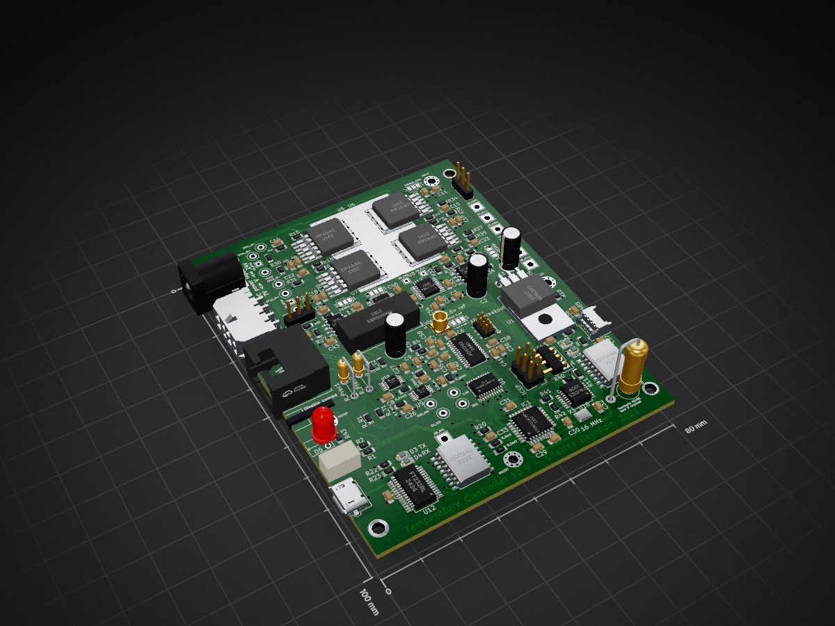
Schematic, PCB and source code for a high-precision digital temperature controller
TempCtrl is an open-source printed circuit board by charlesbaynham, from the charlesbaynham/DigitalTemperatureController repository on GitHub. It is a 4-layer board of 80 × 100 mm with 186 parts on 155 nets, routed with 1,677 tracks and 227 vias.
It is built around the ATMEGA328P-AU, 74LS125DC and ISO3088-Y, with the TMA0505S, RS485 and OPA548T among its other parts. Its parts include 54 capacitors, 39 resistors, 19 ICs, 10 connectors and 6 diodes. It belongs with the AVR (ATmega, ATtiny) boards of this library.


Copyright Charles Baynham 2018
This repository holds a design for a digital temperature controller. The controller is designed for taking high precision temperature measurements via a thermistor and applying low bandwidth PID feedback in response.
This README file gives a brief overview of the device, but a much more detailed description is available in the manual, located in
./Manual.
./Board design contains schematics and PCB layouts for the controller board. This was produced in the open-source software KiCad.
./Code_for_microcontroller contains the C++ code that must run on the on-board microcontroller.
./Code for Labview contains a sample LabView application for controlling the device. See warning below...
Output is by OPA458 high power opamps. Output can be up to 1A continuous, at voltages up to ±15V depending on the power supply.
Error signal acquisition is done by taking a balanced measurement between a thermistor and a set resistor. The board produces an excitation voltage and measures the difference in current between the thermistor and resistor to produce a temperature measurement. For less demanding applications the set resistor can be on-board. For the highest stability, the precision resistor should be placed next to its paired thermistor. This measurement is performed by an INA330 chip, of which there are two present on the board. The entire analogue section is electrically isolated from the rest of the board to prevent noise on the electrical ground affecting the measurement.
The board can be controlled using a (virtual) serial connection over either USB or RS-485. Both of these interfaces are galvanically isolated to prevent electrical interference. The on-board microcontroller permits headless operation of the device, and commands may be issued using a LabView interface.
The code running on the device is written in c++ and has been well tested. The LabView control interface, designed to be run on a monitoring computer, is less well-tested and should be used at your own peril! For integration into an experimental system, control the device by issuing serial commands detail in the supplied manual.
You should go read it now. It's in ./Manual.
The board is designed to break out the important analog (and come digital) connections, so that additional functionality can be enabled by adding a daughter-board to the main board. For example, you might
None of these daughter-boards yet exist, but the interface required to create them exists from V5 onwards.
The microcontroller needs to be flashed using Atmel Studio and an ISP programmer. You should either:
fuse_settings.txtoptiboot_atmega328_custom_NANO.hexOR
.elf file stored in .\Code_for_microcontroller using Atmel Studio, making sure to select "Flash", "Fuses" and "Verify Device ID" in Atmel Studio. This will give you whatever version of the code was stored in this .elf file, you can then update it using the Arduino IDE if you want to make changes.| Qty | Value | Footprint | References |
|---|---|---|---|
| 22 | 100n | Capacitor_SMD:C_0805_2012Metric_Pad1.15x1.40mm_HandSolder | C12, C13, C20, C21, C26, C27, C29, C31, C33, C34, C37, C38, C43, C45, C46, C47 +6 |
| 17 | 100R | Resistor_SMD:R_0805_2012Metric_Pad1.15x1.40mm_HandSolder | R1, R2, R3, R4, R21, R22, R23, R26, R29, R30, R31, R34, R37, R38, R39, R43 +1 |
| 16 | 1u | Capacitor_SMD:C_0805_2012Metric_Pad1.15x1.40mm_HandSolder | C3, C4, C6, C7, C10, C11, C18, C19, C28, C35, C36, C40, C41, C48, C55, C56 |
| 13 | 10k | Resistor_SMD:R_0805_2012Metric_Pad1.15x1.40mm_HandSolder | R9, R11, R24, R25, R27, R28, R32, R33, R35, R36, R40, R41, R42 |
| 7 | PIN | TestPoint:TestPoint_THTPad_3.0x3.0mm_Drill1.5mm | DB_5V1, DB_GND1, DB_GND2, DB_GND3, DB_VCC1, DB_VCC2, DB_VCC3 |
| 6 | Jumper_NO_Small | Custom:SmallJumperNoCourtyard | JP2, JP3, JP4, JP5, JP6, JP7 |
| 5 | MountingHole_2.2mm_M2_Pad_Via | MountingHole:MountingHole_2.2mm_M2_Pad_Via | MOUNT, MOUNT, MOUNT, MOUNT, MOUNT |
| 4 | 100p | Capacitor_SMD:C_0805_2012Metric_Pad1.15x1.40mm_HandSolder | C14, C15, C22, C23 |
| 4 | 15p | Capacitor_SMD:C_0805_2012Metric_Pad1.15x1.40mm_HandSolder | C42, C44, C49, C51 |
| 4 | 1k | Resistor_SMD:R_0805_2012Metric_Pad1.15x1.40mm_HandSolder | R_Ser1, R_Ser2, R10, R20 |
| 4 | 1k_prec | Resistor_SMD:R_0805_2012Metric_Pad1.15x1.40mm_HandSolder | R_R1, R_R2, R_T1, R_T2 |
| 4 | 200K | Resistor_SMD:R_0805_2012Metric_Pad1.15x1.40mm_HandSolder | R13, R15, R17, R19 |
| 4 | 51K | Resistor_SMD:R_0805_2012Metric_Pad1.15x1.40mm_HandSolder | R12, R14, R16, R18 |
| 4 | OPA548 | Custom:TO-263-7Lead | U5, U6, U7, U8 |
| 4 | PIN | TestPoint:TestPoint_THTPad_1.5x1.5mm_Drill0.7mm | DB_ES1, DB_ES2, DB_OPA1, DB_OPA2 |
| 3 | 22k_prec | Resistor_SMD:R_0805_2012Metric_Pad1.15x1.40mm_HandSolder | R_gain1, R_gain2, R_Prec4 |
| 2 | 10k_prec | Custom:Resistor_Vertical_RM5mm_Cust | R_Prec1, R_Prec2 |
| 2 | 10n | Capacitor_SMD:C_0805_2012Metric_Pad1.15x1.40mm_HandSolder | C8, C9 |
| 2 | 1n | Capacitor_SMD:C_0805_2012Metric_Pad1.15x1.40mm_HandSolder | C_filter1, C_filter2 |
| 2 | 47u | Capacitors_ThroughHole:C_Radial_D5_L11_P2 | C2, C5 |
| 2 | 8p | Capacitor_SMD:C_0805_2012Metric_Pad1.15x1.40mm_HandSolder | C30, C32 |
| 2 | AD8639 | Housings_SOIC:SOIC-8_3.9x4.9mm_Pitch1.27mm | U14, U16 |
| 2 | DAC8564 | Housings_SSOP:TSSOP-16_4.4x5mm_Pitch0.65mm | U15, U17 |
| 2 | INA330 | Housings_SSOP:MSOP-10_3x3mm_Pitch0.5mm | U9, U10 |
| 1 | 2.5V | TestPoint:TestPoint_Loop_D2.50mm_Drill1.0mm | W3 |
| 1 | 22u | Capacitors_ThroughHole:C_Radial_D5_L11_P2 | C1 |
| 1 | 233-2977 | Custom:Molex_Microfit3_Header_02x04_Angled_43045-080x_FIXED | P1 |
| 1 | 33k_prec | Resistor_SMD:R_0805_2012Metric_Pad1.15x1.40mm_HandSolder | R_Prec3 |
| 1 | 4.7n | Capacitor_SMD:C_0805_2012Metric_Pad1.15x1.40mm_HandSolder | C39 |
| 1 | 5V_ISO | TestPoint:TestPoint_Loop_D2.50mm_Drill1.0mm | W4 |
| 1 | 5V_Outputs_1 | Connector_PinHeader_2.54mm:PinHeader_1x03_P2.54mm_Vertical | J1 |
| 1 | 5V_Outputs_2 | Connector_PinHeader_2.54mm:PinHeader_1x03_P2.54mm_Vertical | J3 |
| 1 | 74LS125 | Package_SO:SSOP-14_5.3x6.2mm_P0.65mm | U18 |
| 1 | 820-8104 | Custom:RJ45_TE | P2 |
| 1 | ADC breakout | Pin_Headers:Pin_Header_Straight_2x04_Pitch1.27mm | P6 |
| 1 | ADS1262 | Housings_SSOP:TSSOP-28_4.4x9.7mm_Pitch0.65mm | U13 |
| 1 | ADuM7642CRQZ | Housings_SSOP:SSOP-20_4.4x6.5mm_Pitch0.65mm | U3 |
| 1 | ATMEGA328P-A | Housings_QFP:LQFP-32_7x7mm_Pitch0.8mm | IC1 |
| 1 | BARREL_JACK | Connector_BarrelJack:BarrelJack_Horizontal | CON1 |
| 1 | DISABLE FLASH | Pin_Headers:Pin_Header_Straight_1x03 | JP1 |
| 1 | DISABLE_COMMS | Custom:ApemSwitch | SW1 |
| 1 | Disable_OPA1 | Jumper:SolderJumper-3_P1.3mm_Bridged2Bar12_Pad1.0x1.5mm_NumberLabels | DISABLE_OPA1 |
| 1 | Disable_OPA2 | Jumper:SolderJumper-3_P1.3mm_Bridged2Bar12_Pad1.0x1.5mm_NumberLabels | DISABLE_OPA2 |
| 1 | Disable_OPA3 | Jumper:SolderJumper-3_P1.3mm_Bridged2Bar12_Pad1.0x1.5mm_NumberLabels | DISABLE_OPA3 |
| 1 | Disable_OPA4 | Jumper:SolderJumper-3_P1.3mm_Bridged2Bar12_Pad1.0x1.5mm_NumberLabels | DISABLE_OPA4 |
| 1 | External 2.5v ref | Connector_Coaxial:MMCX_Molex_73415-1471_Vertical | J2 |
| 1 | FT232RL | Housings_SSOP:SSOP-28_5.3x10.2mm_Pitch0.65mm | U12 |
| 1 | GND_ISO | TestPoint:TestPoint_Loop_D2.50mm_Drill1.0mm | W2 |
| 1 | ICSP | Custom:6pin_3x2_Amphenol_75869-131LF | P5 |
| 1 | INA1 | TestPoint:TestPoint_Loop_D2.50mm_Drill1.0mm | W1 |
| 1 | ISO3088 | Housings_SOIC:SOIC-16W_7.5x10.3mm_Pitch1.27mm | U4 |
| 1 | ISO7242 | Housings_SOIC:SOIC-16_7.5x10.3mm_Pitch1.27mm | U11 |
| 1 | LED | Custom:PCB_MOUNT_LED | D6 |
| 1 | LM7805 | Custom:TO220_HORZ | U1 |
| 1 | Led_x2_split | Custom:Double_LEDs | D1 |
| 1 | OPA1_IN+ | TestPoint:TestPoint_Loop_D2.50mm_Drill1.0mm | W5 |
| 1 | OPA1_IN- | TestPoint:TestPoint_Loop_D2.50mm_Drill1.0mm | W6 |
| 1 | OPA2_IN+ | TestPoint:TestPoint_Loop_D2.50mm_Drill1.0mm | W8 |
| 1 | OPA2_IN- | TestPoint:TestPoint_Loop_D2.50mm_Drill1.0mm | W9 |
| 1 | POWER | LEDs:LED_0805 | D2 |
| 1 | RS485 | Connectors_Molex:Molex_PicoBlade_53048-0410_04x1.25mm_Angled | P3 |
| 1 | RS485_TERM | Resistor_THT:R_Axial_DIN0516_L15.5mm_D5.0mm_P5.08mm_Vertical | R8 |
| 1 | RX | LEDs:LED_0805 | D4 |
| 1 | SCLK | LEDs:LED_0805 | D5 |
| 1 | Select V_ref | Jumper:SolderJumper-3_P1.3mm_Bridged2Bar12_Pad1.0x1.5mm_NumberLabels | SELECT_VRef1 |
| 1 | TMA0505S | Custom:SIP_TMA0505 | U2 |
| 1 | TSX-3225 X1E0000210013 | Crystals:crystal_FA238-TSX3225 | X1 |
| 1 | TX | LEDs:LED_0805 | D3 |
| 1 | USB_OTG | Custom:MICRO-B_USB_TOP_MOUNT | P4 |
| 1 | VLIM1 | TestPoint:TestPoint_Loop_D2.50mm_Drill1.0mm | W7 |
| 1 | VLIM2 | TestPoint:TestPoint_Loop_D2.50mm_Drill1.0mm | W10 |
The 184 most common of 186 parts.
It measures 80 × 100 mm and has 4 copper layers, 1.6 mm thick.
186 parts, built around the ATMEGA328P-AU, 74LS125DC, ISO3088-Y and TMA0505S. The full list of its parts is on this page, with links to each part's symbol and footprint where PCBKit's library has them.
From the charlesbaynham/DigitalTemperatureController repository on GitHub, at the commit this page was made from: the board is Board design/PCB_Schematic/TempCtrl.kicad_pcb. PCBKit opens the board in the browser, with nothing to install.
Its repository states no licence, so its author keeps all rights: ask charlesbaynham before reusing the design.
charlesbaynham/GP22_RF_Photon_Correllation
Schematic, PCB and source code for a low-cost TDC interface designed for performing RF--Photon correllation for atomic physics experiments


fgallud/tiva_c_connected
Is a very simple tcp modbus example for the tiva c connected board. It is written in C for the Energia IDE


PaulBichl/vibepcb-smu
VibePCB example: 4-quadrant SMU (+-30 V / +-1 A, USB-C PD, Ethernet) designed with an LLM