2 layers110 × 220 mm
Fin ltm
HekiNav/finland-live-train-map
Some of the LEDs are missing because they were removed after making the initial layout
423 parts7MIT

 CDFER/helsinki-live-train-map
A physical, real-time LED map of the Auckland train network, powered by an ESP32-C3 microcontroller. Train movements are displayed using addressable RGB LEDs, with live data fetched over Wi-Fi.
Helsinki LED Train Map is an open-source printed circuit board by CDFER, from the CDFER/helsinki-live-train-map repository on GitHub, published under the MIT licence. It is a 2-layer board of 249 × 69.5 mm with 441 parts on 361 nets, routed with 3,534 tracks and 841 vias.
It is built around the ESP32-C3FH4, SN74LVC4245APWRE4 and XC6206P332MR, with the WS2812B, MM1W5V6 and SS54 among its other parts. Its parts include 303 diodes, 70 capacitors, 26 resistors, 5 ICs and 3 switches. It belongs with the ESP32 and RISC-V boards of this library.


A physical, real-time LED map of the Auckland train network, powered by an ESP32-C3 microcontroller. Train movements are displayed using addressable RGB LEDs, with live data fetched over Wi-Fi.
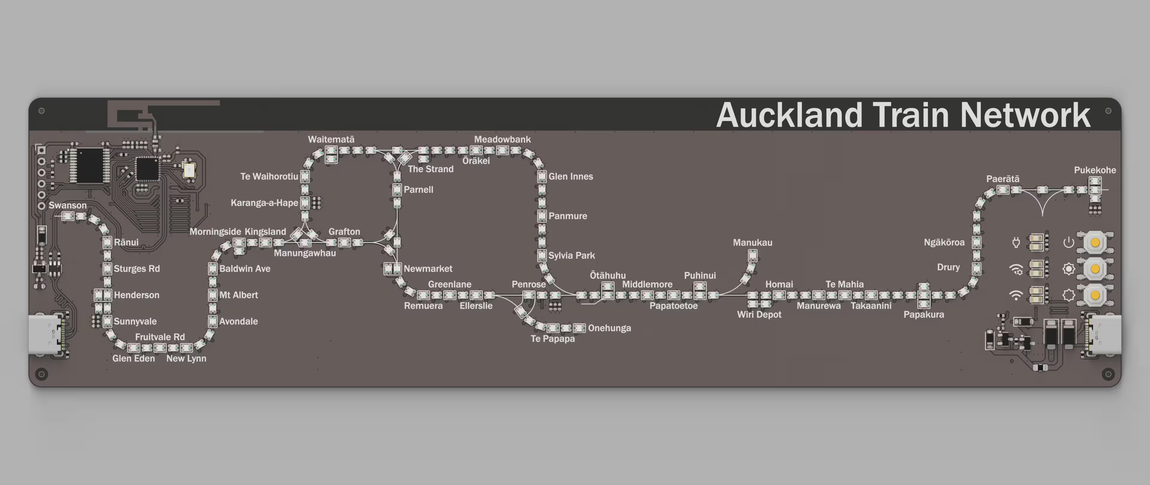
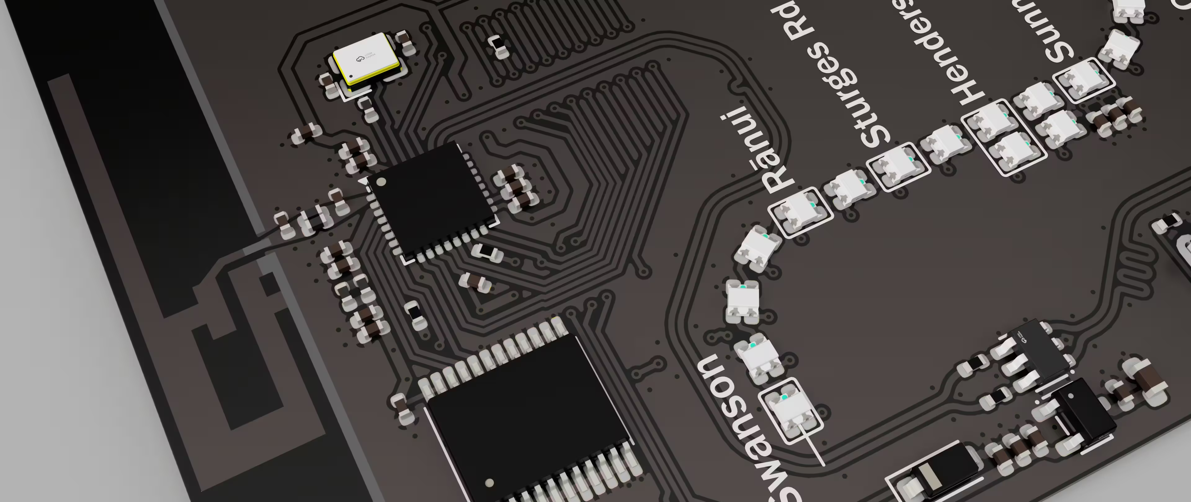
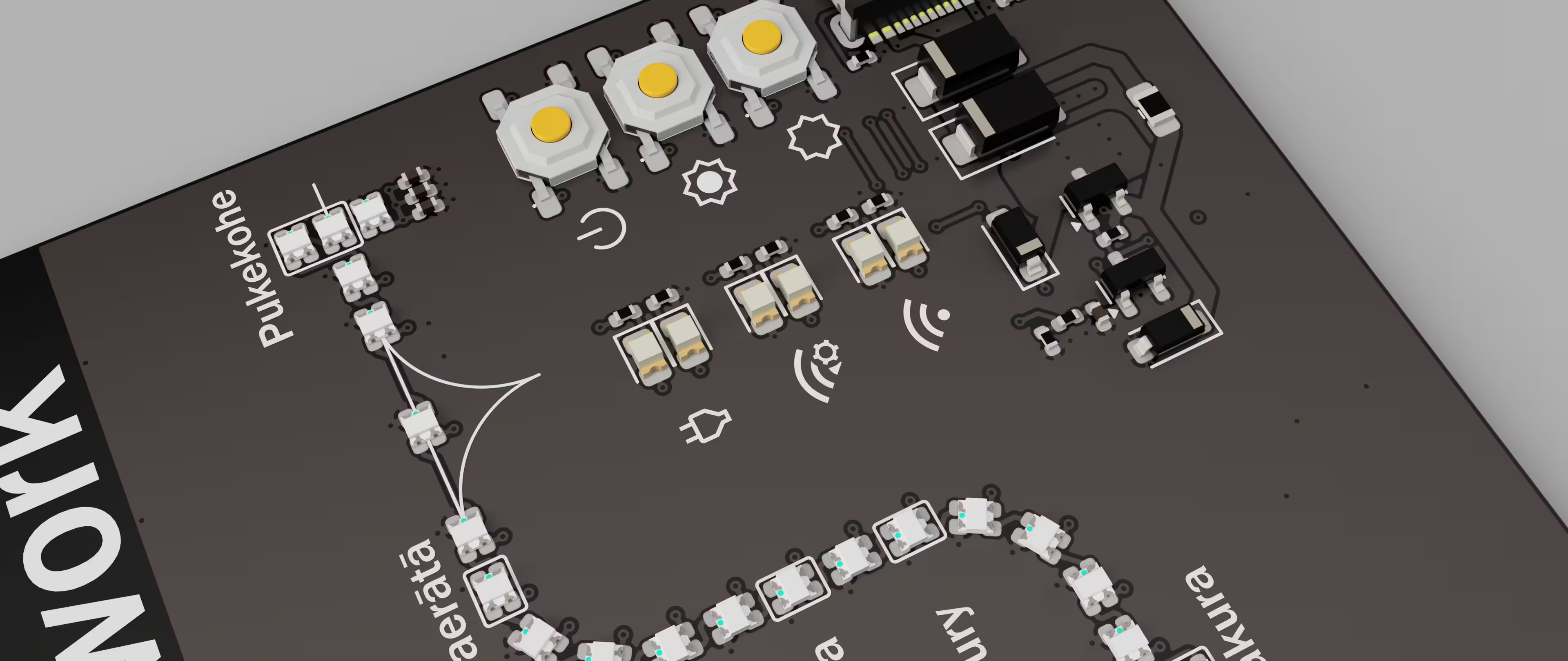
/PCB directory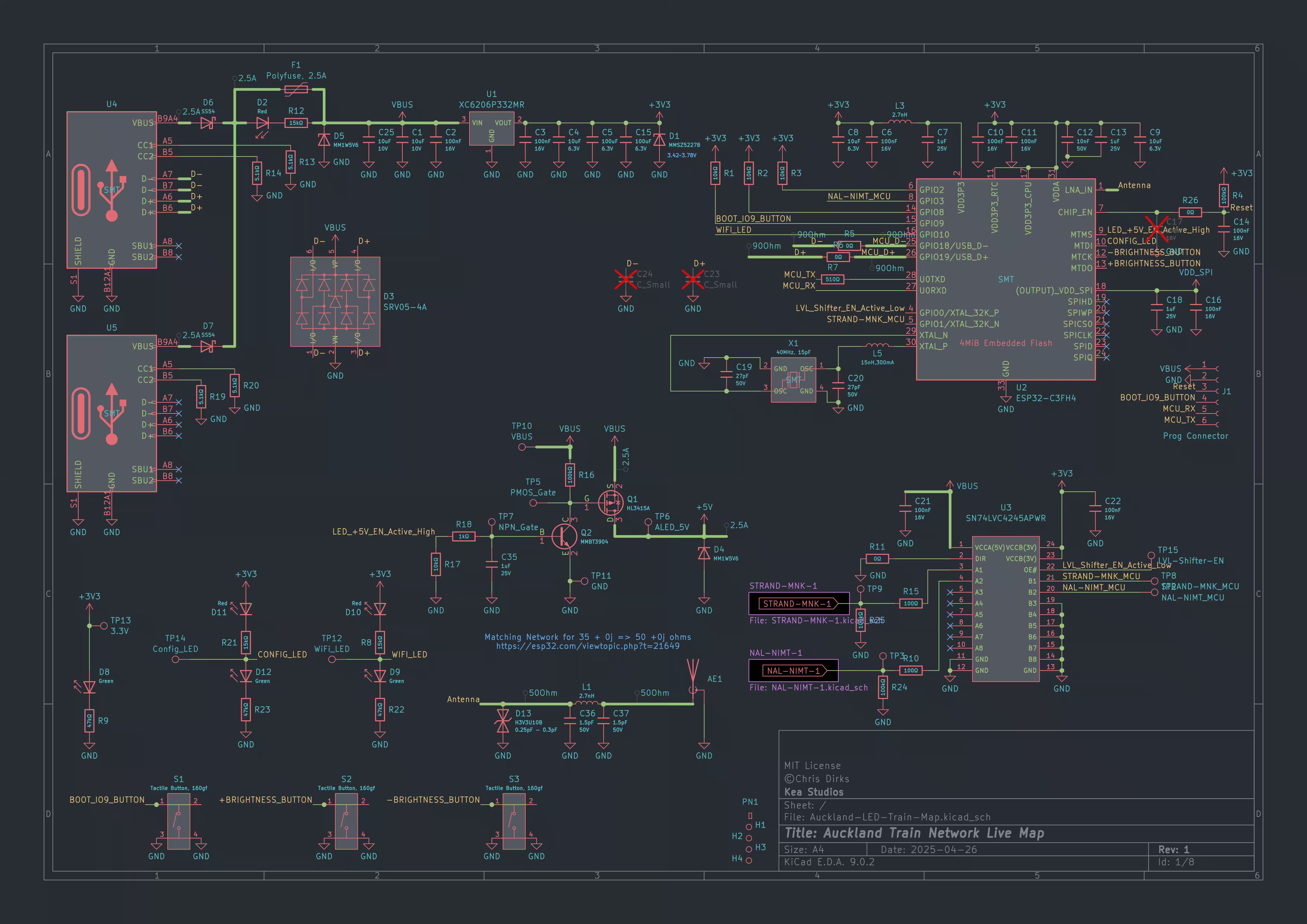
The ESP32-C3 firmware is responsible for:
Firmware/ directory)Easily flash the latest firmware to your ESP32-C3 using your browser:
Open the Auckland LED Train Map Web Installer
Contributions are welcome! Open an issue or submit a pull request for improvements, bug fixes, or feature suggestions.
This project is released under the MIT license.
© 2025 Chris Dirks
| Qty | Value | Footprint | References |
|---|---|---|---|
| 291 | WS2812B | PCM_JLCPCB:LED-SMD_4P-L1.6-W1.5_XL-1615RGBC-WS2812B | D2001, D2002, D2003, D2004, D2005, D2006, D2007, D2008, D2009, D2010, D2011, D2012, D2013, D2014, D2015, D2016 +275 |
| 28 | 220nF | PCM_JLCPCB:C_0402 | C2002, C2003, C2005, C2006, C2008, C2009, C3002, C3003, C3005, C3006, C4002, C4003, C4005, C4006, C4008, C4009 +12 |
| 18 | 10uF | PCM_JLCPCB:C_0402 | C1004, C1006, C1007, C1014, C2001, C2004, C2007, C3001, C3004, C4001, C4004, C4007, C5001, C5004, C5007, C6001 +2 |
| 10 | 100nF | PCM_JLCPCB:C_0402 | C1002, C1003, C1008, C1010, C1011, C1015, C1016, C1020, C1023, C1024 |
| 7 | 100kΩ | PCM_JLCPCB:R_0402 | R1007, R1014, R1019, R1023, R1024, R1025, R1026 |
| 6 | LOGO | LOGO | G***, G***, G***, G***, G***, G*** |
| 4 | 0Ω | PCM_JLCPCB:R_0402 | R1008, R1009, R1010, R1016 |
| 4 | 10kΩ | PCM_JLCPCB:R_0402 | R1004, R1005, R1006, R1017 |
| 4 | 1uF | PCM_JLCPCB:C_0402 | C1009, C1013, C1019, C1026 |
| 4 | 5.1kΩ | PCM_JLCPCB:R_0402 | R1002, R1003, R1012, R1013 |
| 4 | ~ | PCM_JLCPCB:Hole_Tooling_JLCPCB | H1001, H1001, H1002, H1003 |
| 3 | 15kΩ | PCM_JLCPCB:R_0402 | R1001, R1020, R1021 |
| 3 | Green | PCM_JLCPCB:D_0805 | D1009, D1010, D1011 |
| 3 | LOGO | Custom_Footprints:Power | G***, G***, G*** |
| 3 | Red | PCM_JLCPCB:D_0805 | D1002, D1007, D1008 |
| 3 | Tactile Button, 160gf | PCM_JLCPCB:SW-SMD_4P-L5.1-W5.1-P3.70-LS6.5-TL-2 | S1001, S1002, S1003 |
| 2 | 1.5pF | PCM_JLCPCB:C_0402 | C1027, C1028 |
| 2 | 100uF | PCM_JLCPCB:C_CASE-B-3528-21(mm) | C1005, C1025 |
| 2 | 100Ω | PCM_JLCPCB:R_0402 | R1018, R1022 |
| 2 | 2.7nH | PCM_JLCPCB:L_0402 | L1001, L1003 |
| 2 | 27pF | PCM_JLCPCB:C_0402 | C1021, C1022 |
| 2 | C_Small | PCM_JLCPCB:C_0402 | C1017, C1018 |
| 2 | Connector, USB-TYPE-C-16P | PCM_JLCPCB:TYPE-C-SMD_HX-TYPE-C-16PIN | U1002, U1004 |
| 2 | MM1W5V6 | PCM_JLCPCB:D_SOD-123 | D1003, D1006 |
| 2 | SS54 | PCM_JLCPCB:D_SMA | D1001, D1005 |
| 1 | 10nF | PCM_JLCPCB:C_0402 | C1012 |
| 1 | 10uF | PCM_JLCPCB:C_CASE-A-3216-18(mm) | C1001 |
| 1 | 15nH,300mA | PCM_JLCPCB:L_0402 | L1002 |
| 1 | 1kΩ | PCM_JLCPCB:R_0402 | R1015 |
| 1 | 3.3V | Custom_Footprints:TestPoint_Pad_D1.0mm | TP1005 |
| 1 | 40MHz, 15pF | Custom_Footprints:OSC-SMD_4P-L3.2-W2.5-BL_SIT8008BI | X1001 |
| 1 | 510Ω | PCM_JLCPCB:R_0402 | R1011 |
| 1 | Antenna_Shield | Custom_Footprints:Inverted_F_Antenna_2.4Ghz_1.0mmPCB_TI_CC2430DB.pretty | AE1001 |
| 1 | ESP32-C3FH4 | Custom_Footprints:QFN-32-1EP_5x5mm_P0.5mm_EP3.7x3.7mm_ThermalVias | U1003 |
| 1 | H3V3U10B | PCM_JLCPCB:D_DFN1006-2L | D1012 |
| 1 | HKI-KTS_MCU | Custom_Footprints:TestPoint_Pad_D1.0mm | TP1002 |
| 1 | HL3415A | PCM_JLCPCB:Q_SOT-23 | Q1001 |
| 1 | HPL-NOA_MCU | Custom_Footprints:TestPoint_Pad_D1.0mm | TP1003 |
| 1 | LOGO | Custom_Footprints:Brightness_7 | G*** |
| 1 | LOGO | Custom_Footprints:Brightness_0 | G*** |
| 1 | LOGO | Custom_Footprints:WiFi | G*** |
| 1 | LOGO | Custom_Footprints:Mode_Off_ON | G*** |
| 1 | LVL-Shifter-EN | Custom_Footprints:TestPoint_Pad_D1.0mm | TP1001 |
| 1 | MMBT3904 | PCM_JLCPCB:Q_SOT-23 | Q1002 |
| 1 | MMSZ5227B | PCM_JLCPCB:D_SOD-123 | D1004 |
| 1 | NAL-NIMT_LED | Custom_Footprints:TestPoint_Pad_D1.0mm | TP1006 |
| 1 | Polyfuse, 2A | Fuse:Fuse_1206_3216Metric | F1001 |
| 1 | Prog Connector | Custom_Footprints:Prog Connector | J1001 |
| 1 | SN74LVC4245APWR | Package_SO:TSSOP-24_4.4x7.8mm_P0.65mm | U1005 |
| 1 | STRAND-MNK_LED | Custom_Footprints:TestPoint_Pad_D1.0mm | TP1004 |
| 1 | XC6206P332MR | PCM_JLCPCB:SOT-23-3_L2.9-W1.6-P1.90-LS2.8-BR | U1001 |
| 1 | ~ | PCM_JLCPCB:FB_0603 | FB1001 |
| 1 | ~ | PCM_JLCPCB:Part_Num_JLCPCB | PN1001 |
It measures 249 × 69.5 mm and has 2 copper layers, 0.92 mm thick.
441 parts, built around the ESP32-C3FH4, SN74LVC4245APWRE4, XC6206P332MR and WS2812B. The full list of its parts is on this page, with links to each part's symbol and footprint where PCBKit's library has them.
From the CDFER/helsinki-live-train-map repository on GitHub, at the commit this page was made from: the board is PCB/Helsinki-LED-Train-Map.kicad_pcb and its schematic PCB/HKI-KTS-1.kicad_sch. PCBKit opens the board in the browser, with nothing to install.
Its repository publishes it under the MIT licence: you may reuse it on that licence's terms (keep the author's notice, and for a copyleft licence share your changes alike).
HekiNav/finland-live-train-map
Some of the LEDs are missing because they were removed after making the initial layout

CDFER/Melbourne-Live-Train-Map
A curcuit board with RGB leds to show the live position of trains in Melbourne!


Qeteshpony/BratwurstPower
A power supply for a complete, Raspberry Pi based ADS-B Receiver Setup with independent power rails for the different components.

jackw01/scanlight
A better light source for scanning color negative film

stevel1212-droid/stm32-rtc-climate-controller
Kicad project of an STM32-based board climate controller utilizing an RTC module for time-scheduled environmental reading of temperature/humidity with SHT30 sensor and optional small relay for control.

DLehenbauer/econopet
Mainboard replacement for Commodore PET/CBM series machines
