Skip to the content
PCBKitNew board
2 layers330 × 300 mmMelbourne Live Train Map, the printed circuit board in 3D

Melbourne Live Train Map

CDFER/Melbourne-Live-Train-Map5

A curcuit board with RGB leds to show the live position of trains in Melbourne!

Size
330 × 300 mm
Copper layers
2
Thickness
0.92 mm
Parts
1,260
Nets
1,150
Pads
9,014
Tracks, vias
11,327, 1,051
Pours
359
Routed
Yes
KiCad
KiCad 9.0 (file 20241229)
Created
25 Mar 2026
Updated
30 Mar 2026

Overview

Melbourne Live Train Map is an open-source printed circuit board by CDFER, from the CDFER/Melbourne-Live-Train-Map repository on GitHub, published under the GPL-3.0 licence. It is a 2-layer board of 330 × 300 mm with 1,260 parts on 1,150 nets, routed with 11,327 tracks and 1,051 vias.

It is built around the ESP32-S3, LTR-303ALS-01 and MT9700-N, with the RT9080-33GJ5, SN74LVC4245APWRE4 and SS33 among its other parts. Its parts include 1,055 diodes, 130 capacitors, 38 resistors, 9 ICs and 4 switches. It belongs with the lEDs and displays boards and the ESP32 boards of this library.

Main components

8

README

README.md

Melbourne Live Train Map

Hardware, Software and Documentation License: GPL-3.0-or-later Made with KiCad

You can support my work by buying this train map through my store: https://keastudios.co.nz/store/

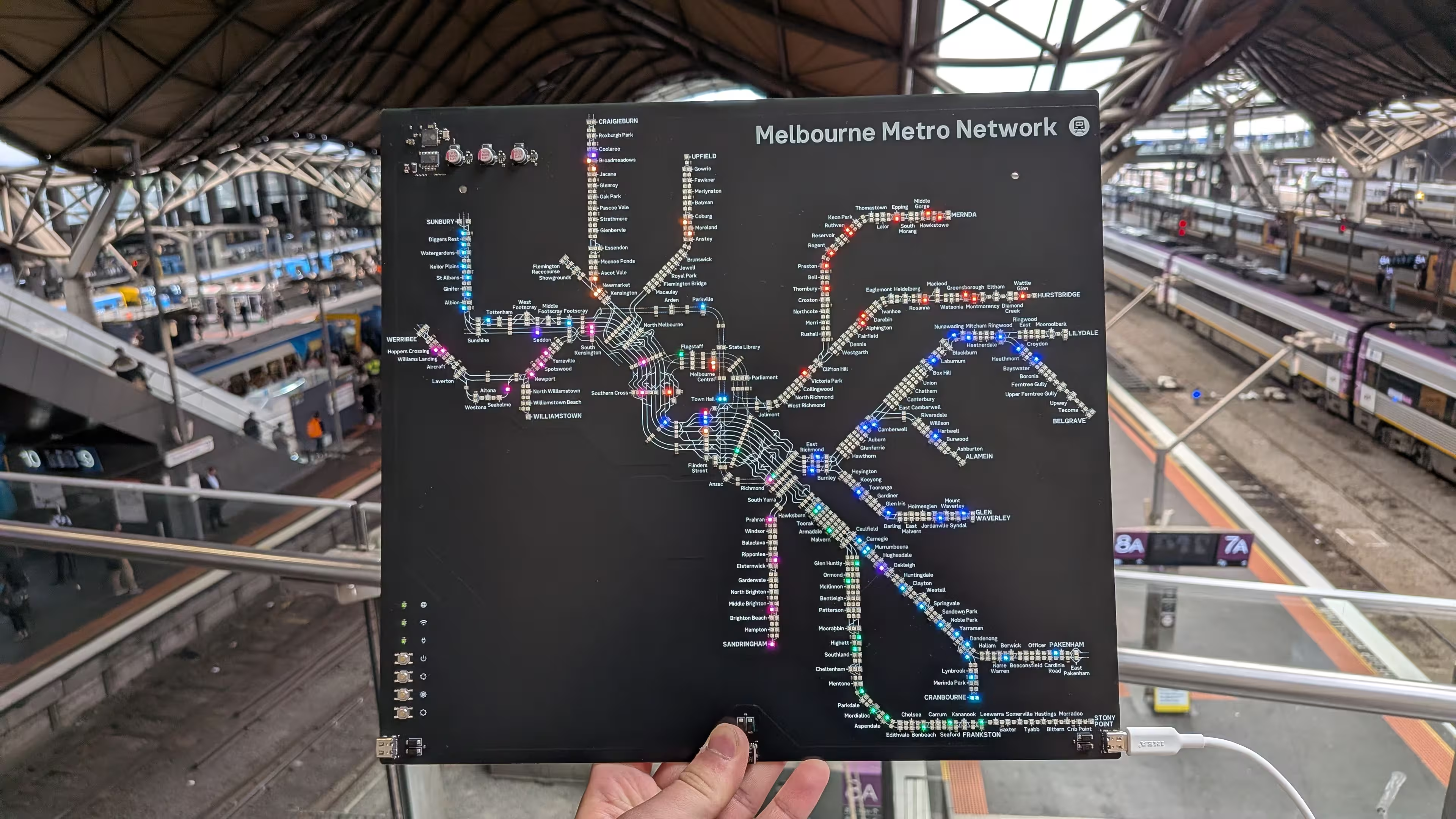
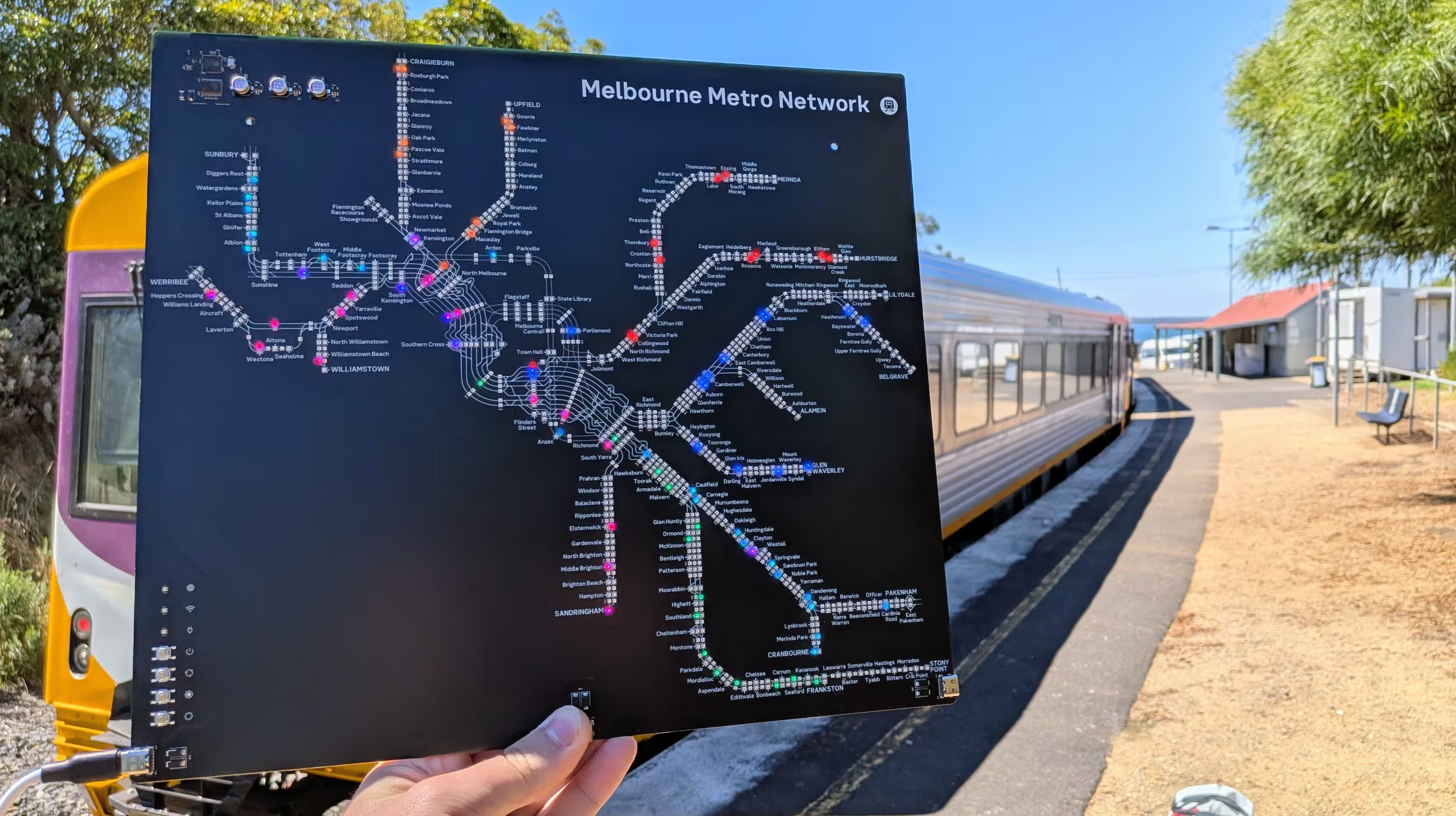
A physical, real-time LED map of the Melbourne train network, powered by an ESP32-S3 microcontroller. Train movements are displayed using addressable RGB LEDs, with live data fetched over Wi-Fi.

Overview_at_Southern_Cross

Features

  • Real-time Train Tracking: Displays the locations of trains on the Melbourne network.
  • Addressable LEDs: WS2812B-compatible RGB LEDs for a vibrant display.
  • Wi-Fi Connectivity: ESP32-S3's built-in Wi-Fi fetches live train data.
  • Adjustable Brightness: You can use the buttons to adjust the brightness of the LEDs.
  • Adaptive Brightness: The circuit board has an ambient light sensor to automatically adjust the brightness of the LEDs.
  • Open Source: Hardware and firmware are open source under GPL-3.0.

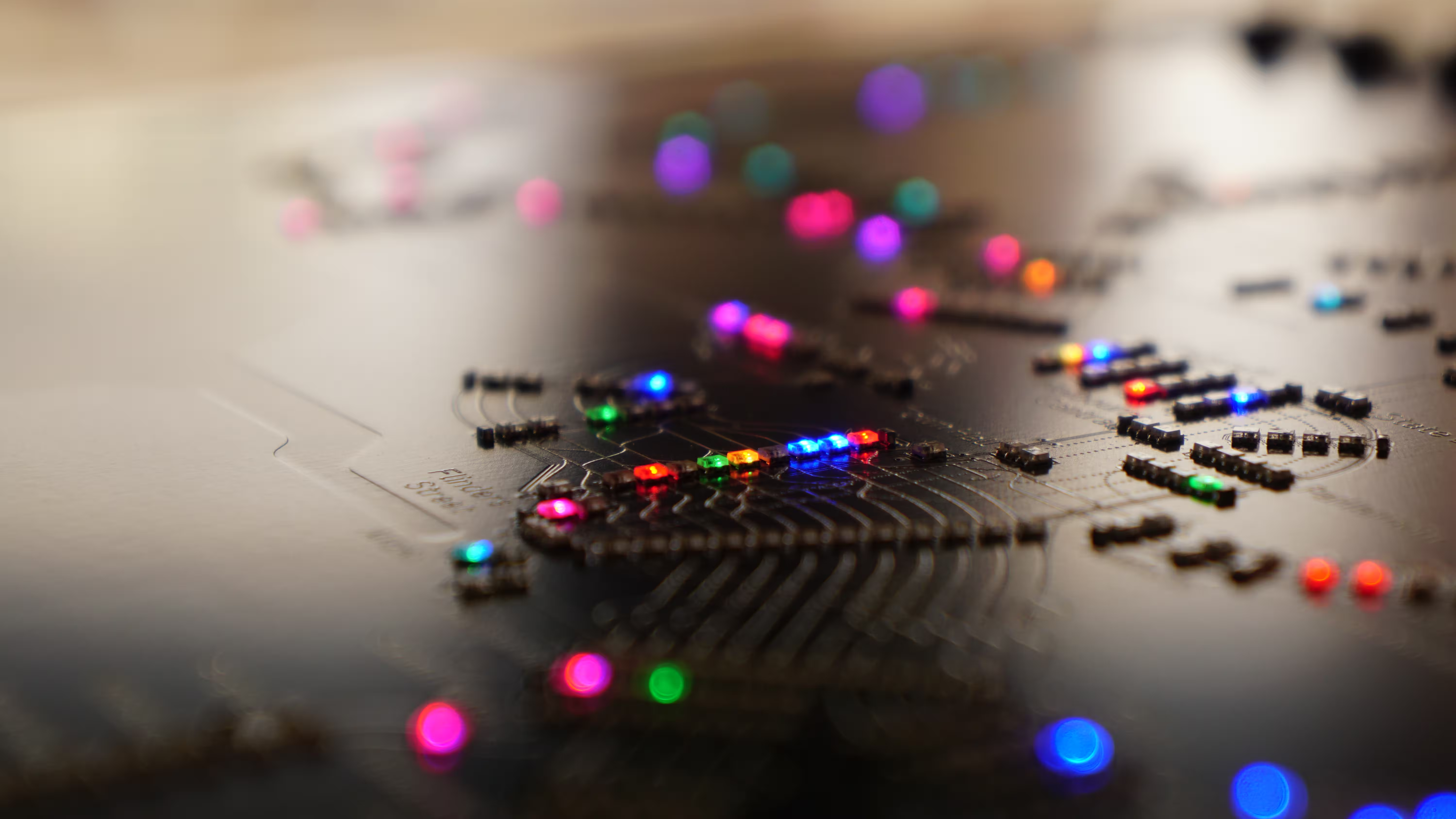
Flinders_St_Close_Up

PCB Design

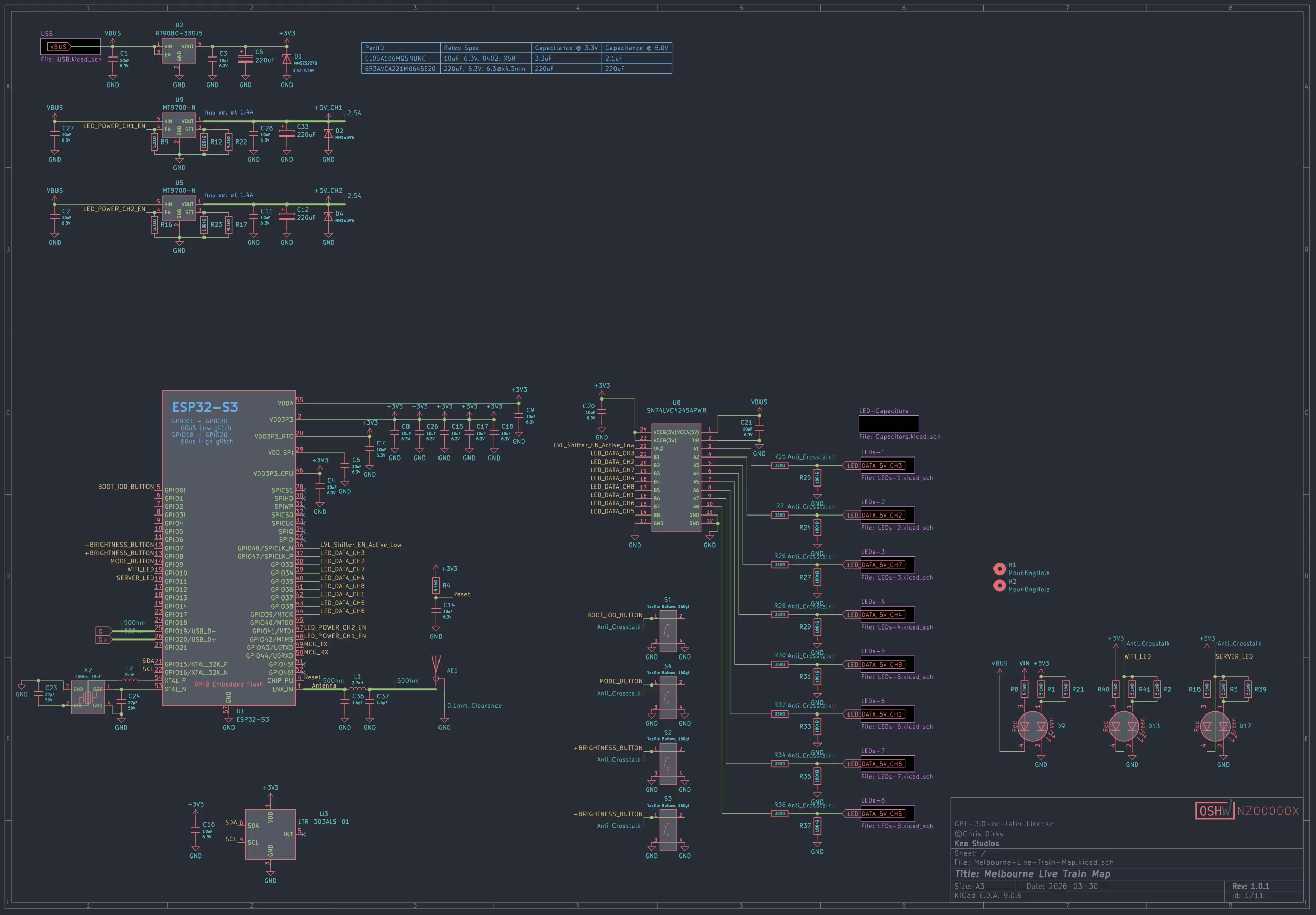
Schematic

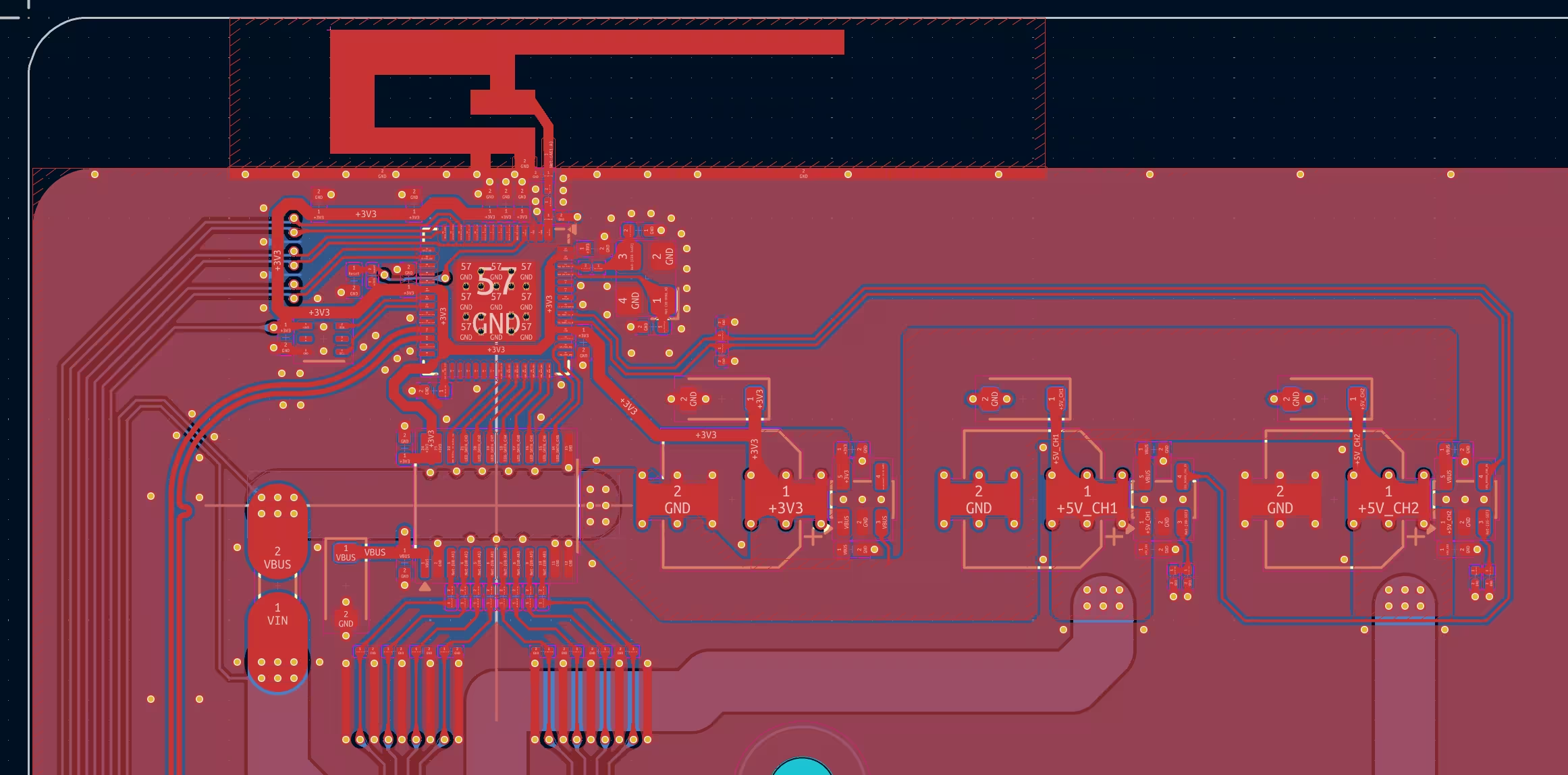
ESP32_PCB

Software / Firmware

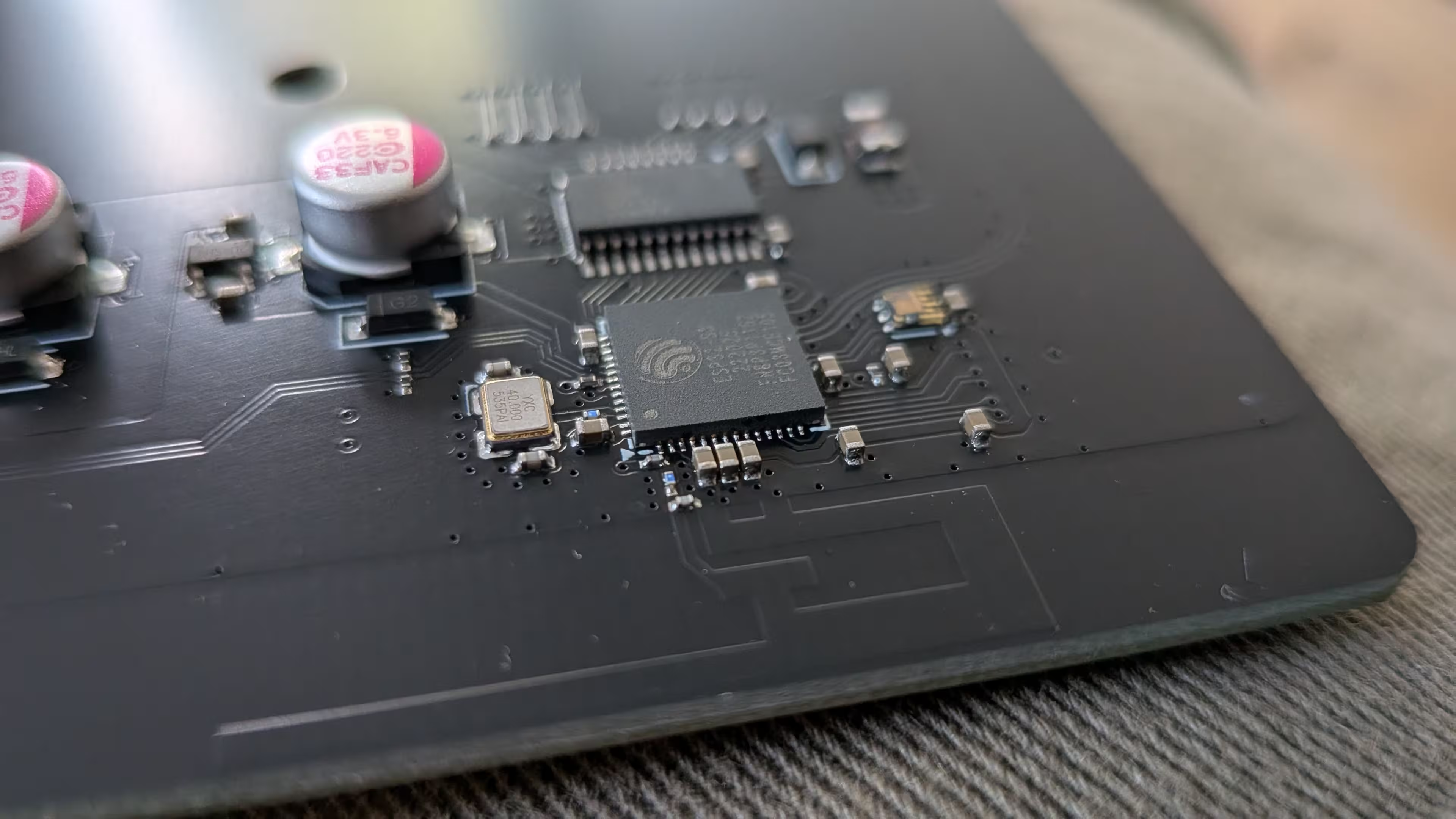
The ESP32-S3 firmware is maintained in a separate repository: LED-Rails-Firmware

ESP32_Close_Up

Contributing

Contributions are welcome! Open an issue or submit a pull request for improvements, bug fixes, or feature suggestions.

Stony_Point_Overview

License

This project is released under the GPL-3.0-or-later license.

© 2026 Chris Dirks

Parts

1,260
QtyValueFootprintReferences
1042XL-1615RGBC-WS2812B-SCustom_Footprints:LED-SMD_4P-L1.6-W1.5_XL-1615RGBC-WS2812BD100, D101, D1000, D1001, D1002, D1003, D1004, D1005, D1006, D1007, D1008, D1009, D1010, D1011, D1012, D1013 +1026
12310uFPCM_JLCPCB:C_0402C1, C10, C11, C100, C101, C102, C103, C104, C105, C106, C107, C108, C109, C110, C111, C112 +107
205.1kΩCustom_Footprints:R_0201_0603MetricR1, R2, R3, R4, R10, R11, R13, R14, R16, R17, R18, R19, R21, R22, R39, R40 +4
10100kΩCustom_Footprints:R_0201_0603MetricR12, R23, R24, R25, R27, R29, R31, R33, R35, R37
8330ΩCustom_Footprints:R_0201_0603MetricR7, R15, R26, R28, R30, R32, R34, R36
8LOGOLOGOG***, G***, G***, G***, G***, G***, G***, G***
6SS33PCM_JLCPCB:D_SMAD3, D6, D7, D14, D15, D16
4LOGOCustom_Footprints:PowerG***, G***, G***, G***
4Tactile Button, 160gfPCM_JLCPCB:SW-SMD_4P-L5.1-W5.1-P3.70-LS6.5-TL-2S1, S2, S3, S4
3220uFCapacitor_SMD:CP_Elec_6.3x4.5C5, C12, C33
3Connector, USB-TYPE-C-16PCustom_Footprints:TYPE-C-SMD_HX-TYPE-C-16PINU4, U6, U7
3LED_Dual,19-223/R7G6C-A01/2TCustom_Footprints:LED-SMD-4P,1.6x1.5mmD9, D13, D17
3MM1W5V6PCM_JLCPCB:D_SOD-123D2, D4, D5
21.4pFCapacitor_SMD:C_0201_0603MetricC36, C37
227pFPCM_JLCPCB:C_0402C23, C24
2MT9700-NPackage_TO_SOT_SMD:SOT-23-5U5, U9
2MountingHole_3.2mm_M3MountingHole:MountingHole_3.2mm_M3H1, H2
12.7nHInductor_SMD:L_0201_0603MetricL1
124nHInductor_SMD:L_0201_0603MetricL2
140MHz, 15pFCustom_Footprints:OSC-SMD_4P-L3.2-W2.5-BL_SIT8008BIX2
1Antenna_ShieldCustom_Footprints:Inverted_F_Antenna_2.4Ghz_1.0mmPCB_TI_CC2430DB.prettyAE1
1ESP32-S3Custom_Footprints:QFN-56-1EP_7x7mm_P0.4mm_EP4x4mm_ThermalViasU1
1LOGOCustom_Footprints:WiFiG***
1LOGOCustom_Footprints:Brightness_0G***
1LOGOCustom_Footprints:Brightness_7G***
1LOGOCustom_Footprints:Mode_Off_ONG***
1LTR-303ALS-01PCM_JLCPCB:Lite-On_LTR-303ALS-01U3
1MMSZ5227BPCM_JLCPCB:D_SOD-123D1
1RT9080-33GJ5Package_TO_SOT_SMD:TSOT-23-5U2
1Resettable FuseFuse:Fuse_1206_3216MetricF1
1SN74LVC4245APWRPackage_SO:TSSOP-24_4.4x7.8mm_P0.65mmU8
1~Custom_Footprints:OSHW-Certification-Mark-Stacked_8x7mm_SilkMaskLOGO2

Questions

How big is the Melbourne Live Train Map PCB?

It measures 330 × 300 mm and has 2 copper layers, 0.92 mm thick.

What parts does the Melbourne Live Train Map use?

1,260 parts, built around the ESP32-S3, LTR-303ALS-01, MT9700-N and RT9080-33GJ5. The full list of its parts is on this page, with links to each part's symbol and footprint where PCBKit's library has them.

Where can I download the Melbourne Live Train Map KiCad files?

From the CDFER/Melbourne-Live-Train-Map repository on GitHub, at the commit this page was made from: the board is PCB/Melbourne-Live-Train-Map.kicad_pcb and its schematic PCB/Capacitors.kicad_sch. PCBKit opens the board in the browser, with nothing to install.

Can I use the Melbourne Live Train Map design in my own project?

Its repository publishes it under the GPL-3.0 licence: you may reuse it on that licence's terms (keep the author's notice, and for a copyleft licence share your changes alike).

Similar boards

  • 2 layers249 × 69.5 mmHelsinki LED Train Map, the printed circuit board in 3D

    Helsinki LED Train Map

    CDFER/helsinki-live-train-map

    A physical, real-time LED map of the Auckland train network, powered by an ESP32-C3 microcontroller. Train movements are displayed using addressable RGB LEDs, with live data fetched over Wi-Fi.

    441 partsMIT
  • 2 layers110 × 220 mmFin ltm, the printed circuit board in 3D

    Fin ltm

    HekiNav/finland-live-train-map

    Some of the LEDs are missing because they were removed after making the initial layout

    423 parts7MIT
  • 2 layers58.3 × 98.2 mmSandKrux, the printed circuit board in 3D

    SandKrux

    sandman21vs/SandKrux

    Placa de desenvolvimento baseada no chip K210, com entradas para touch, câmera e LCD grande, criada especificamente para rodar o firmware Krux.

    176 parts21
  • 4 layers66.9 × 66.9 mmTemp Monitor, the printed circuit board in 3D

    Temp Monitor

    Alex-C-EE/Reliable-Temp-Monitor

    A CAN Node designed to take temperature measurement from 3 analog-output sensors and control 2x 24V fans

    127 parts1
  • 2 layers50 × 50 mmTesi, the printed circuit board in 3D

    Tesi

    EmaNeg/Power_Management_Unit_Tesi

    PMU (Power Management Unit) compatta per sistemi embedded. Integra Power Path automatico, ricarica Li-Po 1S, conversione DC-DC Buck-Boost a 5V e monitoraggio I2C tramite MAX17048.

    65 parts1MIT
  • 2 layers76.5 × 57 mmBuckconverter, the printed circuit board in 3D

    Buckconverter

    GeoffWilliams/usb_buck_converter

    USB powered buck converter 5V -> 3.3V

    15 parts
  • 2 layers111.2 × 76.5 mmThermostat, the printed circuit board in 3D

    Thermostat

    jamesrwaugh/thermostat

    AVR-based Residential Thermostat Hardware / Firmware

    47 parts
  • 4 layers48.3 × 52.9 mmDynaButton, the printed circuit board in 3D

    DynaButton

    manhoosbilli1/dynaboard-button-controller

    Dynaboard - large button/control interface board (102 syms, 590 tracks)

    68 parts