2 layers325 × 235 mm
2023-24 Power Supply
cdagher/BenderPower
Power Supply Hardware and Firmware for the Bender Autonomous Robotics Project
272 partsMIT
 cdagher/BenderPower
Power Supply Hardware and Firmware for the Bender Autonomous Robotics Project
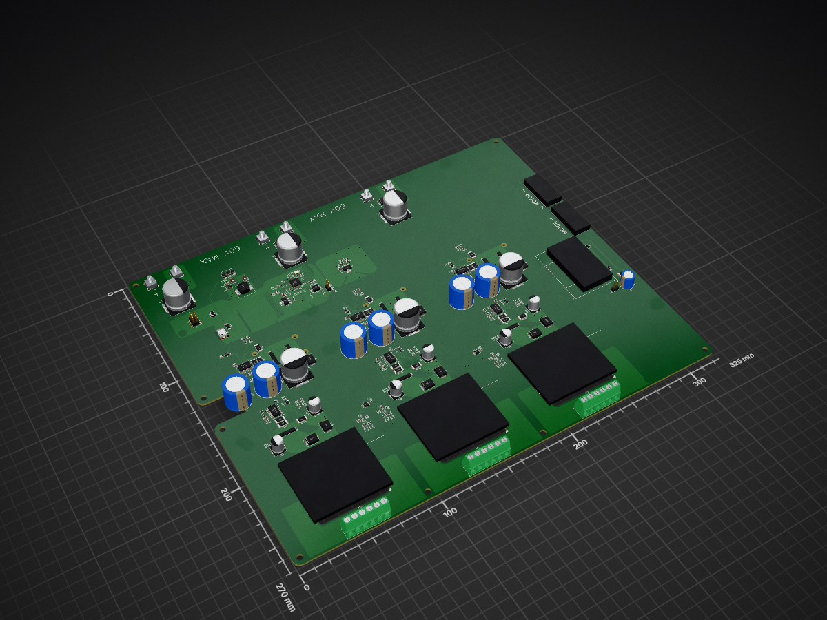
2023-24 Power Supply 2 is an open-source printed circuit board by cdagher, from the cdagher/BenderPower repository on GitHub, published under the MIT licence. It is a 4-layer board of 325 × 270 mm with 320 parts on 235 nets, routed with 2,014 tracks and 467 vias.
It is built around the RP2040, ADS1015IDGS and W25Q128JVSIQ, with the LM5066PMH, MAX17502GATB+ and RCS0603180RFKEA among its other parts. Its parts include 145 resistors, 77 capacitors, 42 transistors, 21 diodes and 16 ICs. It belongs with the power boards and the RP2040 boards of this library.


This repo serves as the home for power supply designs for the Bender Autonomous Robotic Systems (ARS) project at Boise State University. It contains hardware source files including schematics and PCB layout, as well as all firmware source files.
This source is provided as is, with no warranty whatsoever. Feel free to use it in your own projects, so long as you follow the licensing terms.
We wanted our hardware to be flexible, as requirements can change from year to year depending on the goals of our team, design of the robot, and the competition we are targeting. As a result of this, we determined that our power supply should be modular. I don't mean modular like a modular ATX power supply, I mean that we can put in almost any power source, and get almost any supply voltages and currents on the output. This is obviously a tall order, so we settled for an input voltage of 0~60 VDC, a switching capacity of 55 A, and having three replaceable power modules. These modules should be cold-swappable, and can be designed to output nearly any voltage and current within a set power budget. As a final piece, we gave the board three hot-swappable power inputs so that we can power it from multiple batteries or power supplies simultaneously if we want to.
Currently, our power supply is split into three parts as follows:
A switching board which handles up to three inputs which are digitally fused to handle things like over-current, under- and over-voltage conditions, brown-outs, over-temperature conditions. Just to name a few. There are also three slots for our replaceable power modules, and one bank of output terminals for motor drivers directly from the input voltage.
A series of power modules which fit into a "standard" socket. We made a standard for ourselves from off the shelf connectors such that the modules will sit flush with the switching board, in case we need to give them a heatsink.
A controller. Our digital fuses on the inputs and power modules communicate over PMBus, so we need a way of controlling and coordinating everything. As long as the controller fits the bolt pattern and shape specified, it will easily bolt on to the top of the switching board and connect to everything with a wire harness. The decision to break this out into a separate board also simplified design and routing on the switching baord, and allowed for it to be designed for a cheaper 2-layer manufacturing process.
Renderings of the various boards can be seen below.
Switching Board
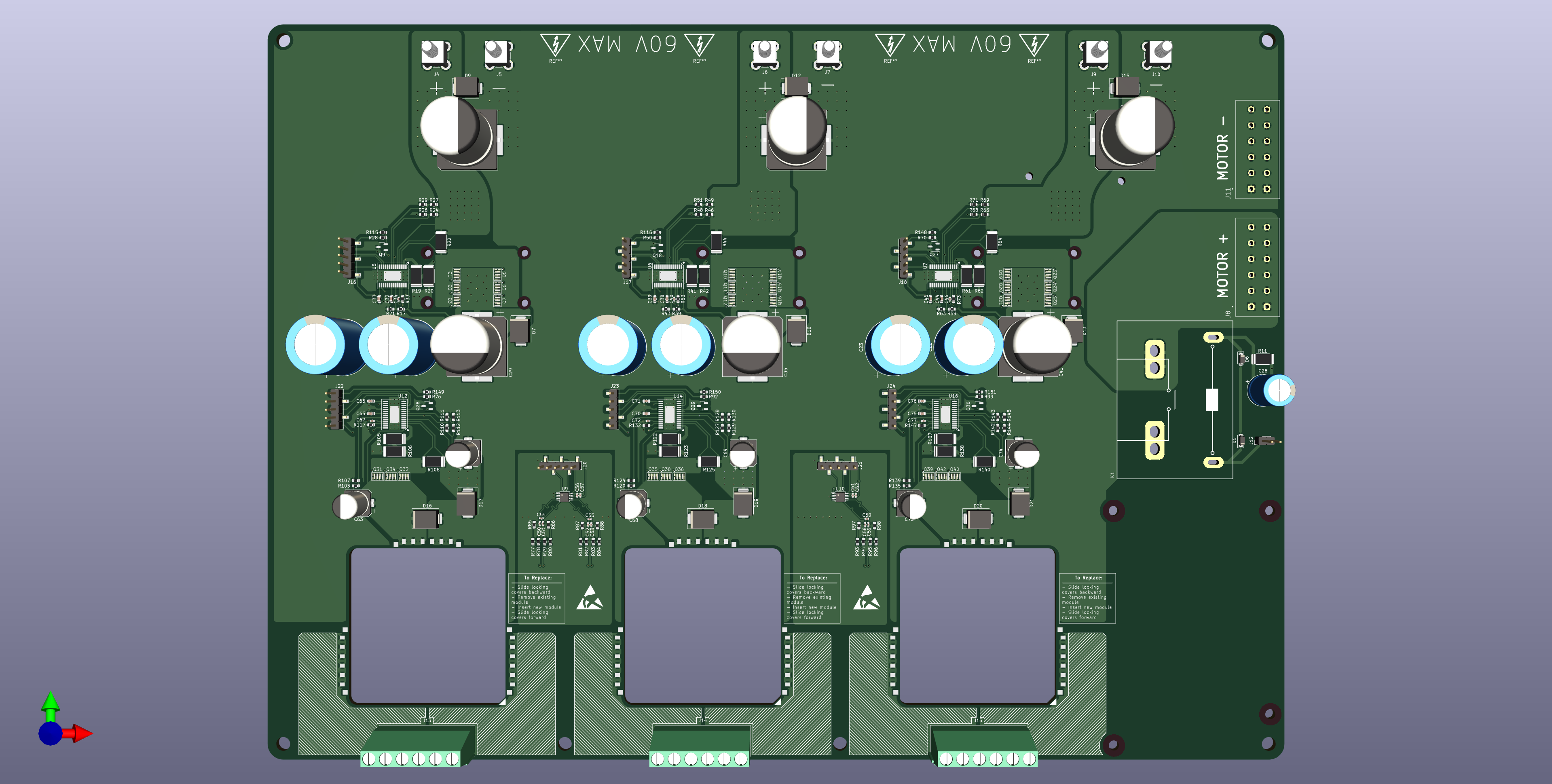 Top view of the switching board
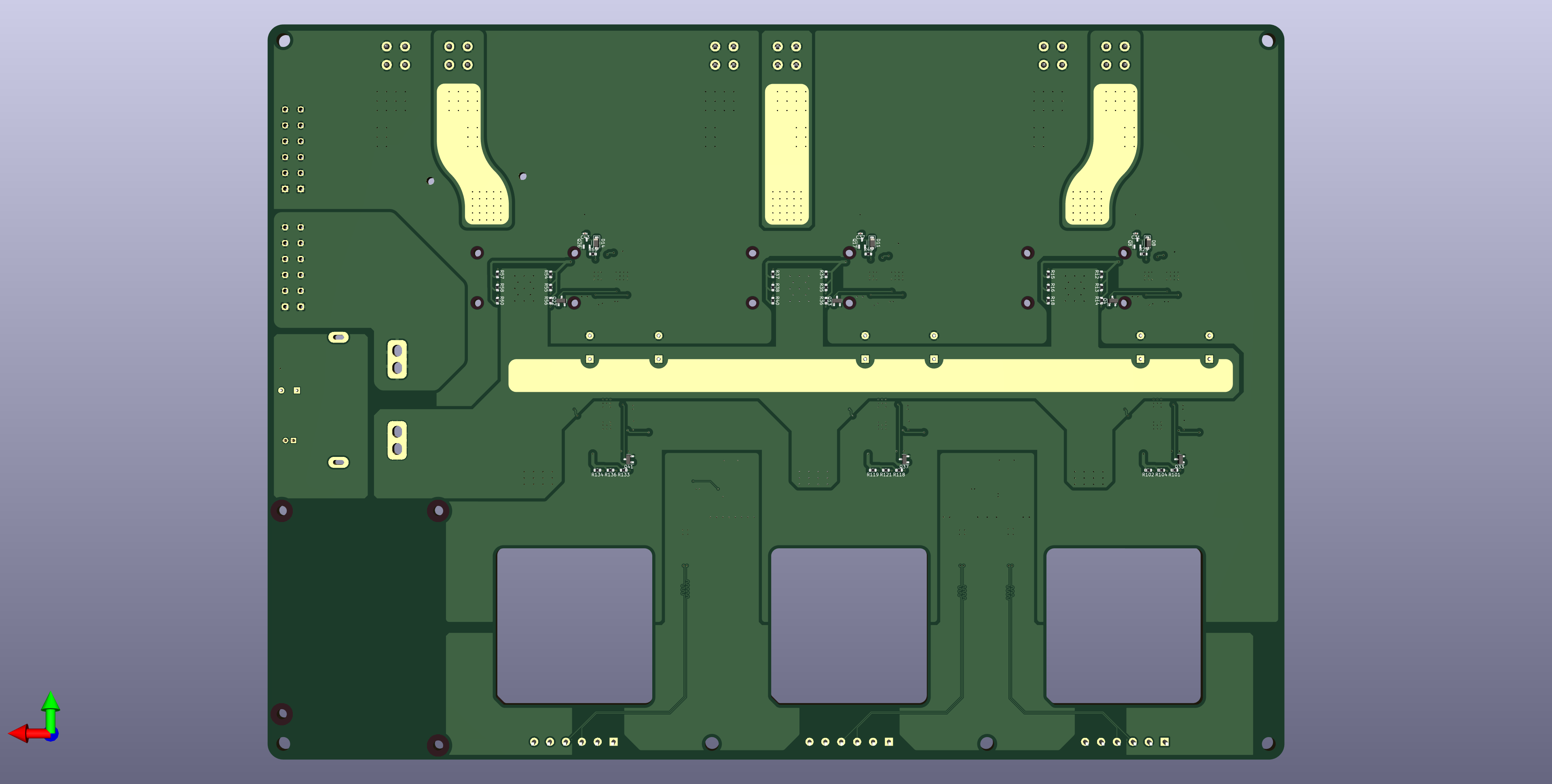 Bottom view of the switching board
Power Module Examples
TODO
Controller
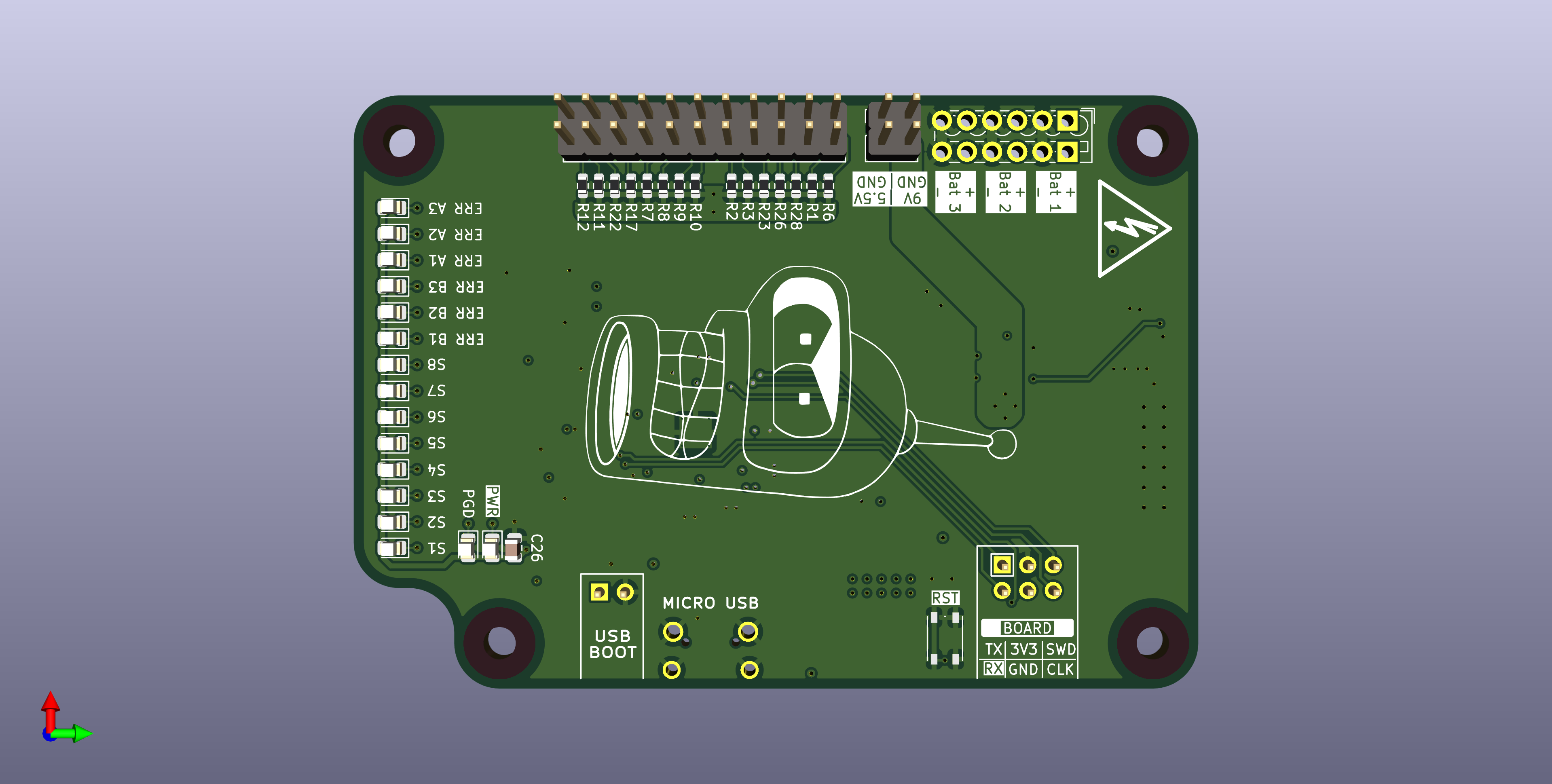 Top view of the controller PCB
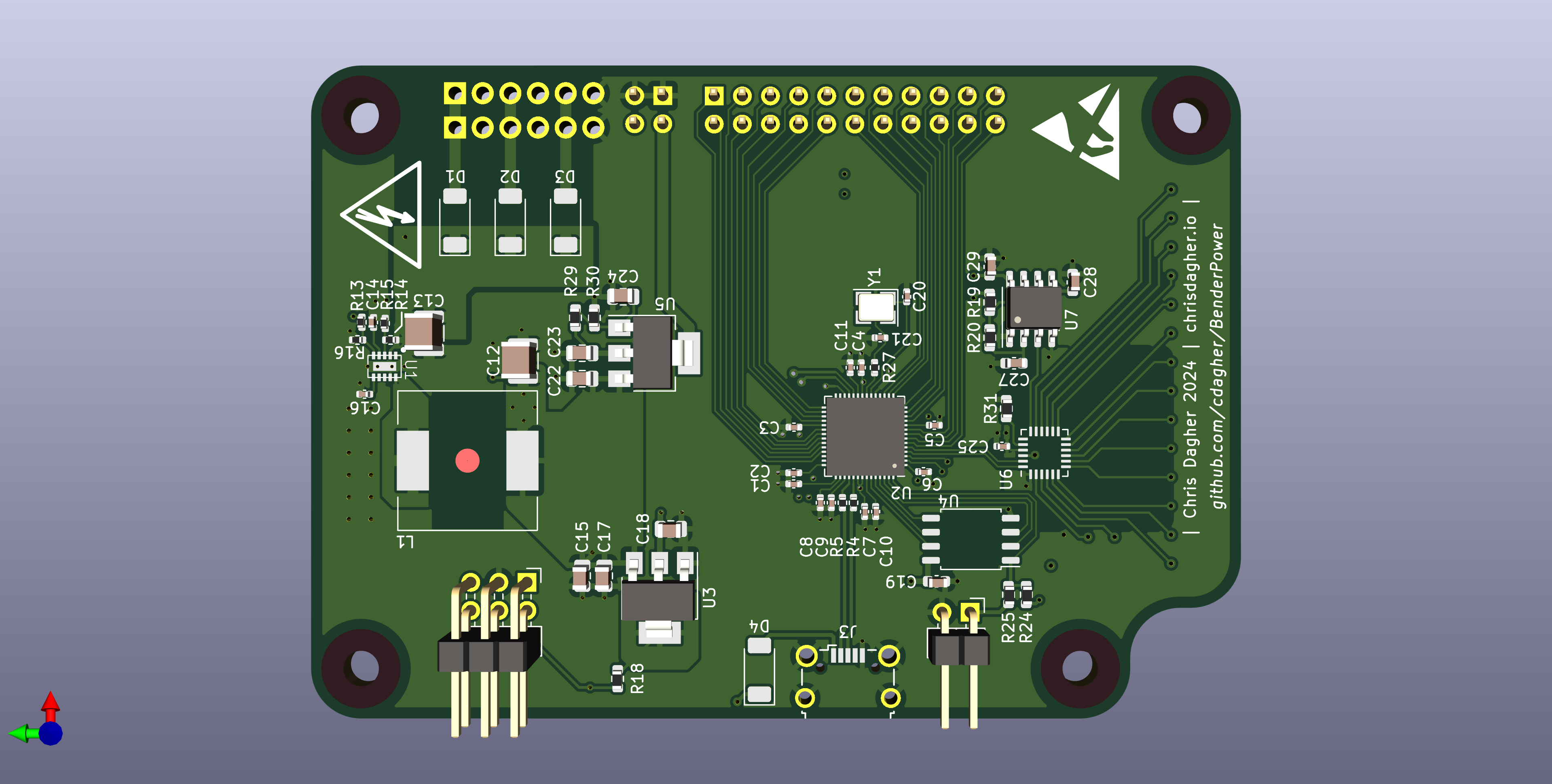 Bottom View of the controller PCB
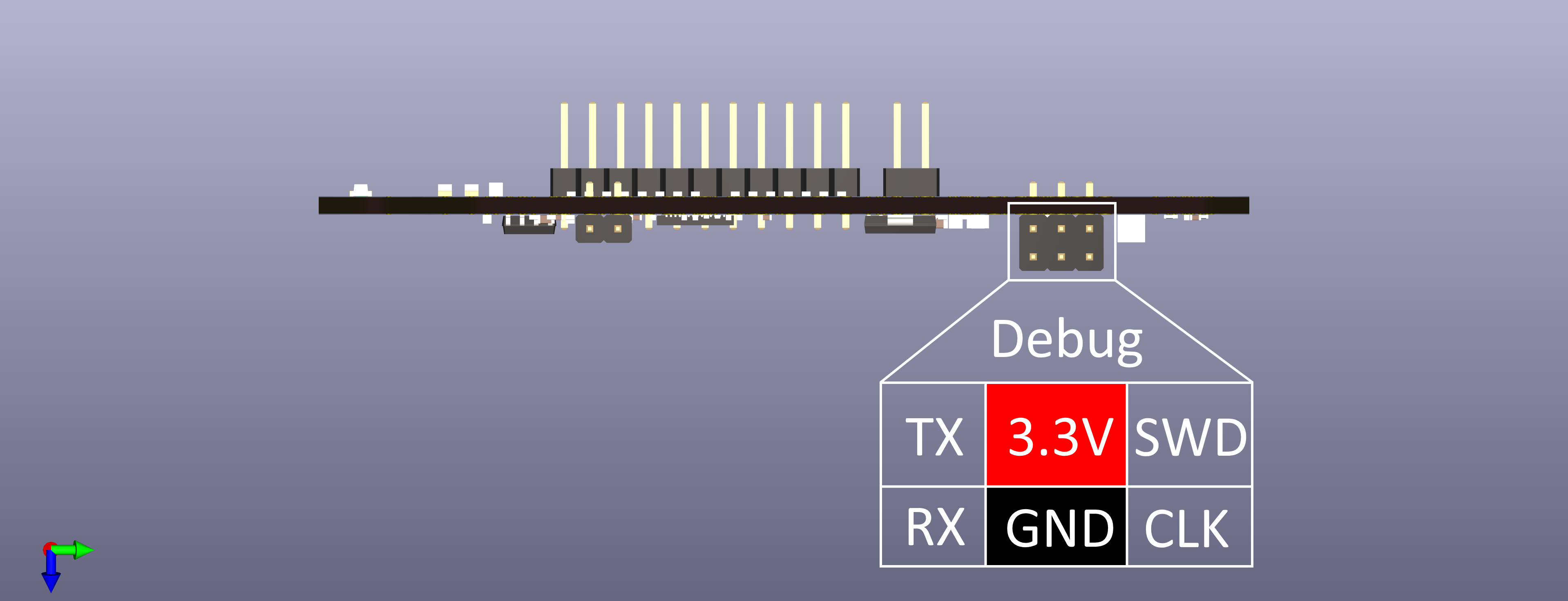 Side view of the controller PCB
TODO
| Qty | Value | Footprint | References |
|---|---|---|---|
| 27 | ~ | Nexperia:WLCSP-8 | Q1, Q2, Q3, Q10, Q11, Q12, Q14, Q15, Q16, Q19, Q20, Q21, Q23, Q24, Q25, Q31 +11 |
| 25 | 10k | Resistor_SMD:R_0603_1608Metric | R7, R30, R31, R32, R52, R72, R78, R79, R82, R83, R85, R86, R100, R114, R131, R146 +9 |
| 24 | 100k | Resistor_SMD:R_0603_1608Metric | R17, R24, R25, R39, R46, R47, R59, R103, R109, R110, R120, R126, R127, R135, R141, R142 +8 |
| 18 | 180 | Resistor_SMD:R_0603_1608Metric | R12, R13, R14, R15, R16, R18, R34, R35, R36, R37, R38, R40, R54, R55, R56, R57 +2 |
| 12 | 1u | Capacitor_SMD:C_0603_1608Metric | C32, C33, C38, C39, C44, C45, C65, C66, C70, C71, C75, C76 |
| 10 | 100n | Capacitor_SMD:C_0402_1005Metric | C1, C2, C3, C4, C5, C6, C7, C10, C11, C19 |
| 9 | 1k | Resistor_SMD:R_0603_1608Metric | R23, R28, R45, R50, R65, R70, R76, R92, R99 |
| 9 | 82.5 | Resistor_SMD:R_0603_1608Metric | R101, R102, R104, R118, R119, R121, R133, R134, R136 |
| 6 | 21.3k | Resistor_SMD:R_0603_1608Metric | R21, R43, R63, R107, R124, R139 |
| 6 | 220u | Capacitor_SMD:CP_Elec_18x17.5 | C29, C30, C35, C36, C41, C42 |
| 6 | 22u | Capacitor_SMD:CP_Elec_8x10 | C63, C64, C68, C69, C73, C74 |
| 6 | 3.9k | Resistor_SMD:R_0603_1608Metric | R29, R51, R71, R113, R130, R145 |
| 6 | 30 | Resistor_SMD:R_2512_6332Metric | R20, R42, R62, R106, R123, R138 |
| 6 | 330u | Capacitor_THT:CP_Radial_D18.0mm_P7.50mm | C22, C23, C24, C25, C26, C27 |
| 6 | 33k | Resistor_SMD:R_0603_1608Metric | R26, R48, R68, R111, R128, R143 |
| 6 | 50n | Capacitor_SMD:C_0402_1005Metric | C50, C51, C52, C53, C58, C59 |
| 6 | 56 | Resistor_SMD:R_2512_6332Metric | R19, R41, R61, R105, R122, R137 |
| 6 | 60V | Diode_SMD:D_SMC | D9, D12, D15, D17, D19, D21 |
| 6 | 80V | Diode_SMD:D_SMC | D7, D10, D13, D16, D18, D20 |
| 6 | 95k | Resistor_SMD:R_0603_1608Metric | R27, R49, R69, R112, R129, R144 |
| 6 | LM5066 | TI:HTSSOP-28 | U5, U6, U7, U12, U14, U16 |
| 6 | NMOS | Package_TO_SOT_SMD:SOT-23-3 | Q9, Q18, Q27, Q28, Q29, Q30 |
| 6 | Screw_Terminal_01x01 | TerminalBlock_Wuerth:Wuerth_REDCUBE-THR_WP-THRSH_74651174_THR | J4, J5, J6, J7, J9, J10 |
| 6 | ~ | Package_TO_SOT_SMD:SOT-23 | Q4, Q13, Q22, Q33, Q37, Q41 |
| 5 | 10u | Capacitor_SMD:C_0805_2012Metric | C15, C17, C18, C47, C48 |
| 4 | PMEG10030ELPX | Diode_SMD:D_SOD-128 | D1, D2, D3, D4 |
| 3 | 1.5m | Resistor_SMD:R_2512_6332Metric | R108, R125, R140 |
| 3 | 100V | Diode_SMD:D_SOD-123 | D8, D11, D14 |
| 3 | 10n | Capacitor_SMD:C_0402_1005Metric | C34, C40, C46 |
| 3 | 1u | Capacitor_SMD:C_0402_1005Metric | C8, C9, C14 |
| 3 | 28.2k | Resistor_SMD:R_0603_1608Metric | R117, R132, R147 |
| 3 | 30n | Capacitor_SMD:C_0402_1005Metric | C31, C37, C43 |
| 3 | 45.3k | Resistor_SMD:R_0603_1608Metric | R33, R53, R73 |
| 3 | 500u | Resistor_SMD:R_2512_6332Metric | R22, R44, R64 |
| 3 | 5p | Capacitor_SMD:C_0402_1005Metric | C54, C55, C60 |
| 3 | 75n | Capacitor_SMD:C_0402_1005Metric | C67, C72, C77 |
| 3 | PNP | Package_TO_SOT_SMD:SOT-23-3 | Q8, Q17, Q26 |
| 3 | Screw_Terminal_01x06 | TerminalBlock_Phoenix:TerminalBlock_Phoenix_MKDS-1,5-6-5.08_1x06_P5.08mm_Horizontal | J13, J14, J15 |
| 3 | ~ | Regulator_Slot:50x50_slot | U11, U13, U15 |
| 2 | 0.1u | Capacitor_SMD:C_0402_1005Metric | C56, C61 |
| 2 | 1.0u | Capacitor_SMD:C_0402_1005Metric | C57, C62 |
| 2 | 1k | Capacitor_SMD:C_0402_1005Metric | R9, R10 |
| 2 | 2.2u | Capacitor_SMD:C_1210_3225Metric | C12, C13 |
| 2 | 27 | Resistor_SMD:R_0402_1005Metric | R1, R2 |
| 2 | 27p | Capacitor_SMD:C_0402_1005Metric | C20, C21 |
| 2 | ADS1015IDGS | Package_SO:TSSOP-10_3x3mm_P0.5mm | U9, U10 |
| 2 | Conn_01x02 | Connector_PinHeader_2.54mm:PinHeader_1x02_P2.54mm_Vertical | J3, J12 |
| 2 | TBL007A-508-06GY | CUI:CUI_TBL007A-508-06GY | J8, J11 |
| 1 | 100k | Resistor_SMD:R_0402_1005Metric | R3 |
| 1 | 11.1k | Resistor_SMD:R_0402_1005Metric | R6 |
| 1 | 120 | Resistor_SMD:R_0603_1608Metric | R74 |
| 1 | 120V | Diode_SMD:D_SOD-123 | D5 |
| 1 | 22u | Capacitor_THT:CP_Radial_D10.0mm_P5.00mm | C28 |
| 1 | 24n | Capacitor_SMD:C_0805_2012Metric | C49 |
| 1 | 3.12k | Resistor_SMD:R_0603_1608Metric | R75 |
| 1 | 3.3M | Resistor_SMD:R_0402_1005Metric | R4 |
| 1 | 36V | Diode_SMD:D_SOD-123 | D6 |
| 1 | 39u | Inductor_SMD:L_12x12mm_H6mm | L1 |
| 1 | 453k | Resistor_SMD:R_0402_1005Metric | R5 |
| 1 | 68 | Resistor_SMD:R_2512_6332Metric | R11 |
| 1 | 910p | Capacitor_SMD:C_0402_1005Metric | C16 |
| 1 | ABLS-12.000MHZ-B4-T | Crystal:Crystal_SMD_Abracon_ABM8G-4Pin_3.2x2.5mm | Y1 |
| 1 | Conn_02x03_Odd_Even | Connector_PinHeader_2.54mm:PinHeader_2x03_P2.54mm_Vertical_SMD | J1 |
| 1 | DNP | Capacitor_SMD:C_0402_1005Metric | R8 |
| 1 | G9KB-1A DC12 | Omron:Relay_SPST_Omron_G9KB | K1 |
| 1 | MAX17502G | Maxim:TDFN | U1 |
| 1 | NCP1117-3.3_SOT223 | Package_TO_SOT_SMD:SOT-223-3_TabPin2 | U3 |
| 1 | NCP1117-ADJ_SOT223 | Package_TO_SOT_SMD:SOT-223-3_TabPin2 | U8 |
| 1 | RP2040 | Package_DFN_QFN:QFN-56-1EP_7x7mm_P0.4mm_EP3.2x3.2mm_ThermalVias | U2 |
| 1 | SW_MEC_5E | Button_Switch_SMD:SW_Push_1P1T_NO_Vertical_Wuerth_434133025816 | SW1 |
| 1 | USB_B_Micro | Connector_USB:USB_Micro-B_Wuerth_629105150521_CircularHoles | J2 |
| 1 | W25Q128JVS | Package_SO:SOIC-8_5.23x5.23mm_P1.27mm | U4 |
cdagher/BenderPower
Power Supply Hardware and Firmware for the Bender Autonomous Robotics Project

cdagher/BenderPower
Power Supply Hardware and Firmware for the Bender Autonomous Robotics Project

BetzDrive/interface-board
Power and signal conditioning board for the Betz Drive system


TU-Darmstadt-APQ/Laser_Backplane_DVI
Laser backplane with DVI connector featuring fast current modulation and a laser diode protection.


darshp848/bldc-controller-60v
60 V, 20 A / 80 A peak BLDC motor controller that fits the MD80 v3.0 mounting. KiCad 10, 6 layers.

It measures 325 × 270 mm and has 4 copper layers, 1.6 mm thick.
320 parts, built around the RP2040, ADS1015IDGS, W25Q128JVSIQ and LM5066PMH. The full list of its parts is on this page, with links to each part's symbol and footprint where PCBKit's library has them.
From the cdagher/BenderPower repository on GitHub, at the commit this page was made from: the board is hardware/2023-24/2023-24_Power_Supply_2.kicad_pcb and its schematic hardware/2023-24/2023-24_Power_Supply.kicad_sch. PCBKit opens the board in the browser, with nothing to install.
Its repository publishes it under the MIT licence: you may reuse it on that licence's terms (keep the author's notice, and for a copyleft licence share your changes alike).