2 layers312.5 × 122.3 mm

 Cbeniaris/TM_Dial
Dial style steering device design for Trackmania 2020
Tm dial pcb is an open-source printed circuit board by Cbeniaris, from the Cbeniaris/TM_Dial repository on GitHub. It is a 2-layer board of 51 × 62.1 mm with 51 parts on 61 nets, routed with 332 tracks and 41 vias.
It is built around the RP2040, W25Q128JVSIQ and AP2112K-3.3. Its parts include 18 capacitors, 9 resistors, 5 connectors, 4 ICs and 1 diode. It belongs with the RP2040 boards of this library.


⚠️ This project is archived and will not be developed further. The hardware is functional as a steering dial only. The 4-button matrix was designed but never implemented. The firmware reflects the current working state: dial axis only, with automatic calibration on startup. PCB files were designed but never manufactured and included an rp2040 and AS5600 for all features.
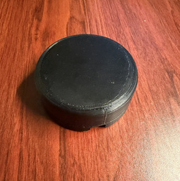
A 3D printed, mechanically self-centering USB HID steering dial built for Trackmania 2020. Driven by QMK firmware on an RP2040 Pro Micro, it presents as a standard joystick — no drivers needed.
| Component | Details |
|---|---|
| MCU | RP2040 Pro Micro (USB-C) |
| Angle sensor | AS5600 carrier board (I2C, 12-bit, 0–359.9°) |
| Magnet | 4mm × 2mm N52 diametrically magnetized disc |
| Bearings | 1x 50mm ID / 65mm OD deep groove ball bearing |
| Center return | 2× extension springs |
| Hard stops | 3D printed mechanical stops |
| Steering travel | 60° total — 30° left and 30° right of center |
| AS5600 Pin | RP2040 Pin | Notes |
|---|---|---|
| VCC | 3.3V | RP2040 is not 5V tolerant — do not use 5V |
| GND | GND | |
| SDA | GP29 | I2C0 data, 400kHz fast mode |
| SCL | GP28 | I2C0 clock |
The AS5600 has internal I2C pull-ups — no external resistors needed in most cases. Most carrier boards include an onboard regulator and are safe at 3.3V.
The dial exposes a single USB HID joystick axis (Axis 0).
| Parameter | Value |
|---|---|
| Total travel | 60° (30° each side of center) |
| AS5600 counts per side | 341 (341/4096 × 360 ≈ 30°) |
| HID output range | -127 (full left) to +127 (full right) |
| Sensor poll rate | 250Hz (every 4ms) |
| USB HID report rate | 125Hz |
Extension springs provide passive center return. The 3D printed hard stops enforce the 30° limit physically; the firmware also clamps in software as a secondary safety. Wrap-around at the 0/4095 AS5600 boundary is handled, so the magnet can be mounted at any rotational position.
The dial calibrates automatically on every startup — the AS5600 reading at power-on is treated as center. Let the dial rest at its physical center position (held by the springs) before plugging in USB.
The firmware also supports EEPROM-based calibration via BTN4 as designed, but since the buttons were never wired, startup calibration is the effective method in the current build.
Copy the keyboard folder into your QMK install:
cp -r keyboards/tm_dial/ /path/to/qmk_firmware/keyboards/Build:
qmk compile -kb tm_dial -km defaultFlash:
qmk flash -kb tm_dial -km defaultRP2040 boot mode: Hold BOOT on the Pro Micro while plugging in USB. The board mounts as a USB mass storage device. QMK flash will copy the
.uf2automatically, or drag-and-drop it manually.
TMDial/
├── README.md
├── tm_dial.FCStd              — FreeCAD source file for all printed parts
│
├── print_files/
│   └── tm_dial-v1-1.bgcode    — PrusaSlicer sliced output ready to print
│
├── firmware/
│   ├──tm_dial_default.uf2     - Compiled firmware ready for flashing
│   └── tm_dial/               — QMK keyboard folder (copy into qmk_firmware/keyboards/)
│       ├── keyboard.json      — USB identity (VID 0x4144 / PID 0x544D), matrix pins, layout
│       ├── rules.mk           — MCU, bootloader, feature flags
│       ├── config.h           — I2C pins, steering range, poll rate, EEPROM offset
│       ├── halconf.h          — Enables HAL I2C driver for ChibiOS/RP2040
│       ├── mcuconf.h          — Enables I2C0, disables I2C1 on RP2040
│       ├── as5600.h           — Sensor driver public API
│       ├── as5600.c           — Sensor I2C read implementation
│       └── keymaps/default/
│           └── keymap.c       — Axis mapping, wrap-around, calibration
│
└── pcb/                       — KiCad PCB project (designed, never fabricated)
    ├── tm_dial_pcb.kicad_pro  — Project file
    ├── tm_dial_pcb.kicad_sch  — Schematic
├── tm_dial_pcb.kicad_pcb — Board layout| Constant | File | Default | Effect |
|---|---|---|---|
STEERING_RANGE_COUNTS | config.h | 341 | Travel range in AS5600 counts (341 ≈ 30° each side) |
AS5600_POLL_MS | config.h | 4 | Sensor read interval in ms — lower = faster response |
JOYSTICK_AXIS_RESOLUTION | config.h | 8 | HID axis bit depth (8-bit = -127 to +127) |
STEERING_CENTER_DEFAULT | config.h | 2048 | Fallback center if EEPROM is blank |
EEPROM_STEERING_CENTER | config.h | 32 | EEPROM byte offset for stored center value |
I2C1_CLOCK_SPEED | config.h | 400000 | I2C bus speed in Hz (400kHz fast mode) |
| Qty | Value | Footprint | References |
|---|---|---|---|
| 12 | 0.1uF | Capacitor_SMD:C_0402_1005Metric | C1, C2, C3, C4, C5, C6, C7, C8, C9, C10, C13, C14 |
| 4 | 1uF | Capacitor_SMD:C_0402_1005Metric | C15, C16, C17, C18 |
| 3 | MountingHole_3.2mm_M3 | MountingHole:MountingHole_3.2mm_M3 | H1, H2, H3 |
| 2 | 1k Ω | Resistor_SMD:R_0402_1005Metric | R7, R15 |
| 2 | 27 Ω | Resistor_SMD:R_0402_1005Metric | R11, R12 |
| 2 | 27pF | Capacitor_SMD:C_0402_1005Metric | C11, C12 |
| 2 | 4.7k Ω | Resistor_SMD:R_0402_1005Metric | R9, R10 |
| 2 | 5.1k Ω | Resistor_SMD:R_0402_1005Metric | R1, R2 |
| 2 | Conn_01x04 | Connector_PinHeader_2.00mm:PinHeader_1x04_P2.00mm_Horizontal | J2, J3 |
| 1 | 12Mhz | Crystal:Crystal_SMD_Abracon_ABM3-2Pin_5.0x3.2mm | Y1 |
| 1 | 680 Ω | Resistor_SMD:R_0603_1608Metric | R13 |
| 1 | AP2112K-3.3 | Package_TO_SOT_SMD:SOT-23-5 | U3 |
| 1 | AS5600-ASOM_SOIC8_LF_T&RDP | AS5600:SOIC8_AS5600_OSR-L | U2 |
| 1 | BOOTSEL | Button_Switch_SMD:SW_Push_SPST_NO_Alps_SKRK | SW1 |
| 1 | Debug | Connector_PinHeader_2.54mm:PinHeader_1x03_P2.54mm_Horizontal | J4 |
| 1 | GPIO_18 | TestPoint:TestPoint_Pad_D1.5mm | TP8 |
| 1 | GPIO_19 | TestPoint:TestPoint_Pad_D1.5mm | TP7 |
| 1 | GPIO_20 | TestPoint:TestPoint_Pad_D1.5mm | TP6 |
| 1 | GPIO_21 | TestPoint:TestPoint_Pad_D1.5mm | TP5 |
| 1 | LED | LED_SMD:LED_0603_1608Metric | D1 |
| 1 | RP2040 | Package_DFN_QFN:QFN-56-1EP_7x7mm_P0.4mm_EP3.2x3.2mm | U1 |
| 1 | Reset | Connector_PinHeader_2.54mm:PinHeader_1x02_P2.54mm_Horizontal | J5 |
| 1 | TP_+3.3V | TestPoint:TestPoint_Pad_D1.5mm | TP3 |
| 1 | TP_GND | TestPoint:TestPoint_Pad_D1.5mm | TP4 |
| 1 | TP_SCL | TestPoint:TestPoint_Pad_D1.5mm | TP1 |
| 1 | TP_SDA | TestPoint:TestPoint_Pad_D1.5mm | TP2 |
| 1 | TP_USB_PWR | TestPoint:TestPoint_Pad_D1.5mm | TP9 |
| 1 | USB_C_Plug_USB2.0 | Connector_USB:USB_C_Receptacle_GCT_USB4110 | J1 |
| 1 | W25Q128JVS | Package_SO:JEITA_SOIC-8_3.9x4.9mm_P1.27mm | U4 |
It measures 51 × 62.1 mm and has 2 copper layers, 1.6 mm thick.
51 parts, built around the RP2040, W25Q128JVSIQ and AP2112K-3.3. The full list of its parts is on this page, with links to each part's symbol and footprint where PCBKit's library has them.
From the Cbeniaris/TM_Dial repository on GitHub, at the commit this page was made from: the board is pcb/tm_dial_pcb.kicad_pcb and its schematic pcb/tm_dial_pcb.kicad_sch. PCBKit opens the board in the browser, with nothing to install.
Its repository states no licence, so its author keeps all rights: ask Cbeniaris before reusing the design.

ianklug/grooveboard
A four-key mechanical keyboard for rhythm games.

ianklug/bemini
A miniature mechanical keyboard controller with a rotary encoder for staggered-key rhythm games.

yuz207/agentpad13
agentpad13 — open-source 13-key macropad for agentic work (RP2040, vial-qmk, planar joystick, Raw HID agent-status protocol)

jpconstantineau/EncoderPad_RP2040
The EncoderPad RP2040 is a Video Editing Macropad with a 60mm Encoder Wheel. This encoder is made of metal and feels like it will last forever. The EncoderPad uses 9 mechanical switches (Cherry MX type).


Isaac-Duarte/wellfed
Open firmware that runs the PETLIBRO Granary PLAF103 pet feeder on your own Wi-Fi: no cloud, no account. Early and in testing.
