2 layers58.3 × 98.2 mm
SandKrux
sandman21vs/SandKrux
Placa de desenvolvimento baseada no chip K210, com entradas para touch, câmera e LCD grande, criada especificamente para rodar o firmware Krux.
176 parts21
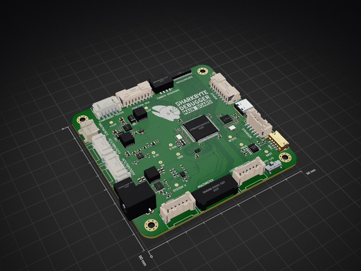
 CausticLime1/Debugging-Board1
The purpose of this project is to develop a budget-friendly electronics debugging station that includes various PCBs (Printed Circuit Boards) that incorporate different functionalities.
Debugging Board is an open-source printed circuit board by CausticLime1, from the CausticLime1/Debugging-Board repository on GitHub. It is a 6-layer board of 90 × 90 mm with 166 parts on 157 nets, routed with 1,935 tracks and 365 vias.
It is built around the CH224K, LM61460AASQRJRRQ1 and TPS65131RGE, with the USB3300-EZK, SM05B-PASS-TBT(LF)(SN) and SM06B-PASS-TBT(LF)(SN) among its other parts. Its parts include 72 capacitors, 35 resistors, 25 ICs, 5 diodes and 3 inductors. It belongs with the sensors and measurement and interfaces and adapters boards and the STM32 boards of this library.


The purpose of this project is to develop a budget-friendly electronics debugging station that includes various PCBs (Printed Circuit Boards) that incorporate different functionalities. A self-designed main board will be used to handle the data processing to display the outputs of the various peripheral boards. The peripheral boards will each have their own functionality and use such as an oscilloscope, multimeter, function generator, logic analyzer, variable DC power supply, and CAN Bus debugger. Each board will have a data connector utilizing various GPIO and communication protocols such as UART, SPI, and PSSI as well as a power connector that is handled by the power management system on the main board.
The central board that all peripheral boards connects to and handles data processing pipeline to a computer. This board has a power management system uses a central 5V rail to provide to a 3.3V LDO for microcontroller logic, and +-12V for operational amplifiers.
| Qty | Value | Footprint | References |
|---|---|---|---|
| 28 | 100nF | Capacitor_SMD:C_0402_1005Metric | C2, C10, C12, C14, C15, C17, C18, C20, C25, C26, C28, C29, C30, C32, C33, C36 +12 |
| 10 | 10uF | Capacitor_SMD:C_0603_1608Metric | C1, C4, C21, C22, C23, C27, C37, C51, C65, C70 |
| 10 | TestPoint | TestPoint:TestPoint_Pad_D2.0mm | TP1, TP2, TP3, TP4, TP5, TP6, TP7, TP9, TP10, TP11 |
| 6 | 1uF | Capacitor_SMD:C_0603_1608Metric | C16, C40, C54, C55, C56, C60 |
| 6 | 22uF | Capacitor_SMD:C_0805_2012Metric | C52, C53, C64, C67, C71, C72 |
| 5 | 10K | Resistor_SMD:R_0402_1005Metric | R12, R14, R15, R22, R29 |
| 5 | SM05B-PASS-TBT(LF)(SN) | JLC_PARTS:CONN-SMD_5P-P2.00_SM05B-PASS-TBT-LF-SN | U12, U15, U16, U17, U23 |
| 4 | 15pF | Capacitor_SMD:C_0402_1005Metric | C3, C8, C24, C31 |
| 4 | 1K | Resistor_SMD:R_0402_1005Metric | R25, R28, R34, R35 |
| 4 | 4.7uF | Capacitor_SMD:C_0603_1608Metric | C11, C38, C41, C48 |
| 4 | MountingHole_Pad | MountingHole:MountingHole_3.2mm_M3_Pad_Via | H1, H2, H3, H4 |
| 3 | 100K | Resistor_SMD:R_0402_1005Metric | R19, R24, R31 |
| 3 | 10K | Resistor_SMD:R_0603_1608Metric | R7, R10, R18 |
| 3 | 600R@100MHz | Inductor_SMD:L_0805_2012Metric | FB1, FB2, FB8 |
| 3 | FNR6045S4R7 | Inductor_SMD:L_Changjiang_FNR6045S | L1, L2, L3 |
| 3 | LED | LED_SMD:LED_0603_1608Metric | D1, D4, D5 |
| 3 | SM06B-PASS-TBT(LF)(SN) | JLC_PARTS:CONN-SMD_SM06B-PASS-TBT | U20, U21, U26 |
| 2 | 10nF | Capacitor_SMD:C_0402_1005Metric | C44, C61 |
| 2 | 10pF | Capacitor_SMD:C_0402_1005Metric | C47, C50 |
| 2 | 120K | Resistor_SMD:R_0603_1608Metric | R8, R17 |
| 2 | 120R@100MHz | Inductor_SMD:L_0603_1608Metric | FB4, FB6 |
| 2 | 12K | Resistor_SMD:R_0402_1005Metric | R3, R4 |
| 2 | 1nF | Capacitor_SMD:C_0402_1005Metric | C6, C19 |
| 2 | 2.2uF | Capacitor_SMD:C_0603_1608Metric | C9, C13 |
| 2 | 22K | Resistor_SMD:R_0402_1005Metric | R20, R21 |
| 2 | 4.7K | Resistor_SMD:R_0402_1005Metric | R32, R33 |
| 2 | 4.7uF | Capacitor_SMD:C_0402_1005Metric | C34, C35 |
| 2 | SM03B-PASS-TBT(LF)(SN)_C412099 | JLC_PARTS:CONN-SMD_SM03B-PASS-TBT | U18, U19 |
| 2 | SM08B-PASS-TBT(LF)(SN) | JLC_PARTS:CONN-SMD_SM08B-PASS-TBT-LF-SN | U11, U14 |
| 2 | SS34 | Diode_SMD:D_SMA | D2, D3 |
| 1 | 100R | Resistor_SMD:R_0402_1005Metric | R6 |
| 1 | 10k | Resistor_SMD:R_0402_1005Metric | R2 |
| 1 | 150K | Resistor_SMD:R_0603_1608Metric | R13 |
| 1 | 1K | Resistor_SMD:R_0603_1608Metric | R30 |
| 1 | 200K | Resistor_SMD:R_0402_1005Metric | R16 |
| 1 | 220nF | Capacitor_SMD:C_0402_1005Metric | C46 |
| 1 | 22R | Resistor_SMD:R_0402_1005Metric | R5 |
| 1 | 22pF | Capacitor_SMD:C_0402_1005Metric | C68 |
| 1 | 24K | Resistor_SMD:R_0603_1608Metric | R1 |
| 1 | 27K | Resistor_SMD:R_0603_1608Metric | R11 |
| 1 | 30K | Resistor_SMD:R_0603_1608Metric | R26 |
| 1 | 33K | Resistor_SMD:R_0402_1005Metric | R23 |
| 1 | 33K | Resistor_SMD:R_0603_1608Metric | R9 |
| 1 | 4.7nF | Capacitor_SMD:C_0402_1005Metric | C45 |
| 1 | 47pF | Capacitor_SMD:C_0402_1005Metric | C49 |
| 1 | 7.5K | Resistor_SMD:R_0603_1608Metric | R27 |
| 1 | AO3401A | Rocketry_Easyeda:SOT-23_L2.9-W1.3-P1.90-LS2.4-BR | Q1 |
| 1 | APS6404L-3SQR-ZR | Rocketry_Easyeda:USON-8_L3.0-W2.0-P0.50-BL-EP | U3 |
| 1 | Barrel_Jack_Switch | Connector_BarrelJack:BarrelJack_Kycon_KLDX-0202-xC_Horizontal | J1 |
| 1 | CH224K | Package_SO:SSOP-10-1EP_3.9x4.9mm_P1mm_EP2.1x3.3mm | U1 |
| 1 | FFC2B28-24-G | JLC_PARTS:FPC-SMD_24P-P0.50_XKB_X05A10L24G | U10 |
| 1 | LM61460AASQRJRRQ1 | Rocketry_Easyeda:VQFN-14-HR_L4.0-W3.5-TL_LM61460AASQRJRRQ1 | U8 |
| 1 | LOGO | LOGO | G*** |
| 1 | S5B-ZR-SM4A-TF(LF)(SN) | JLC_PARTS:CONN-SMD_5P-P1.50_S5B-ZR-SM4A-TF-LF-SN | U9 |
| 1 | SM02B-PASS-TBT(LF)(SN) | JLC_PARTS:CONN-SMD_SM02B-PASS-TBT | U13 |
| 1 | SM04B-PASS-TBT(LF)(SN) | JLC_PARTS:CONN-SMD_SM04B-PASS-TBT-LF-SN | U24 |
| 1 | SM09B-PASS-TBT(LF)(SN) | JLC_PARTS:CONN-SMD_SM09B-PASS-TBT | U22 |
| 1 | STM32H723VGTx | Package_QFP:LQFP-100_14x14mm_P0.5mm | U2 |
| 1 | SW_SPDT | Button_Switch_SMD:SW_SPDT_CK_JS102011SAQN | SW1 |
| 1 | TPS2121RUXR | Rocketry_Easyeda:VQFN-HR-12_L2.5-W2.0-P0.50-BL | U6 |
| 1 | TPS65131RGE | Package_DFN_QFN:VQFN-24-1EP_4x4mm_P0.5mm_EP2.45x2.45mm_ThermalVias | U5 |
| 1 | TPS7A9401DSCR | Rocketry_Easyeda:WSON-10_L3.0-W3.0-P0.50-TL-EP | U7 |
| 1 | TYPE-C 16PIN 2MD(073) | Rocketry_Easyeda:USB-C-SMD_TYPE-C-6PIN-2MD-073 | USB1 |
| 1 | USB3300-EZK | Package_DFN_QFN:QFN-32-1EP_5x5mm_P0.5mm_EP3.45x3.45mm | U4 |
| 1 | X322524MOB4SI | Crystal:Crystal_SMD_3225-4Pin_3.2x2.5mm | Y2 |
| 1 | X322525MOB4SI | Crystal:Crystal_SMD_3225-4Pin_3.2x2.5mm | Y1 |
It measures 90 × 90 mm and has 6 copper layers, 1.6 mm thick.
166 parts, built around the CH224K, LM61460AASQRJRRQ1, TPS65131RGE and USB3300-EZK. The full list of its parts is on this page, with links to each part's symbol and footprint where PCBKit's library has them.
From the CausticLime1/Debugging-Board repository on GitHub, at the commit this page was made from: the board is Electrical/MainBoard/DebuggingBoard.kicad_pcb and its schematic Electrical/FunctionGenerator/FuncGenBoard/FuncGenBoard.kicad_sch. PCBKit opens the board in the browser, with nothing to install.
Its repository states no licence, so its author keeps all rights: ask CausticLime1 before reusing the design.
sandman21vs/SandKrux
Placa de desenvolvimento baseada no chip K210, com entradas para touch, câmera e LCD grande, criada especificamente para rodar o firmware Krux.

loozhengyuan/MitsubishiSC
Smart controller for Mitsubishi Electric HVAC systems.


LimesKey/parsnip-node
A portable LoRa communicator. Custom 4-layer PCB (ESP32-S3 + E22P-915M30S LoRa + NEO-M9N GNSS), designed in KiCad for 915 MHz.

Accelerator6666/Yaesu-FT2D-USBC-charge
检查日期:2026-10-26;KiCad 10.0.7;目标板厂:嘉立创 JLCPCB;目标工艺:4 层 PCB + SMT 代贴片。

danbrunski/canary
Four 25 F cells in series for CANary-PWR's LTC3350 hold-up, on a lead (design record: docs/CANary-PWR-Spec.md §P4). The board has no active parts: four cells, an NTC, two Kelvin net ties and a Micro-Fit 2 × 5 header.

Mig-M27/Avionics-PCBs
Este repositório é usado para gerir as versões dos projetos KiCAD do sistema de Avionics da Porto Space Team. Está dividido em 2 secções: 1.