2 layers138.4 × 80.3 mm

 catinella/HILO1
Hardware In the LOop
IOlinesManagement is an open-source printed circuit board by catinella, from the catinella/HILO repository on GitHub. It is a 4-layer board of 138.4 × 80.3 mm with 156 parts on 194 nets, routed with 1,440 tracks and 64 vias.
It is built around the MIC4427ZM, BC327 and BC817. Its parts include 80 resistors, 32 transistors, 16 capacitors, 16 switches and 8 ICs.


| Files/Dirs | Description |
|---|---|
| firmware | The firmware for manager MCU |
| PCB | All the PCBs used in the project |
| console | The software used to manage the HILO |
| images | Images and diagrams used by README.md |
| lgpl-3.0.txt | L-GPL ver 3.0 license document |
The goal of this project is to get a device that allows the user to test an electronic system in an easy way, also remotely. In the 1990 when I was studying at high scool, who was developing new devices, used generic boxes with buttons, switches, LEDs, displays.... installed on it. This device allowed him to emulate the external environment.
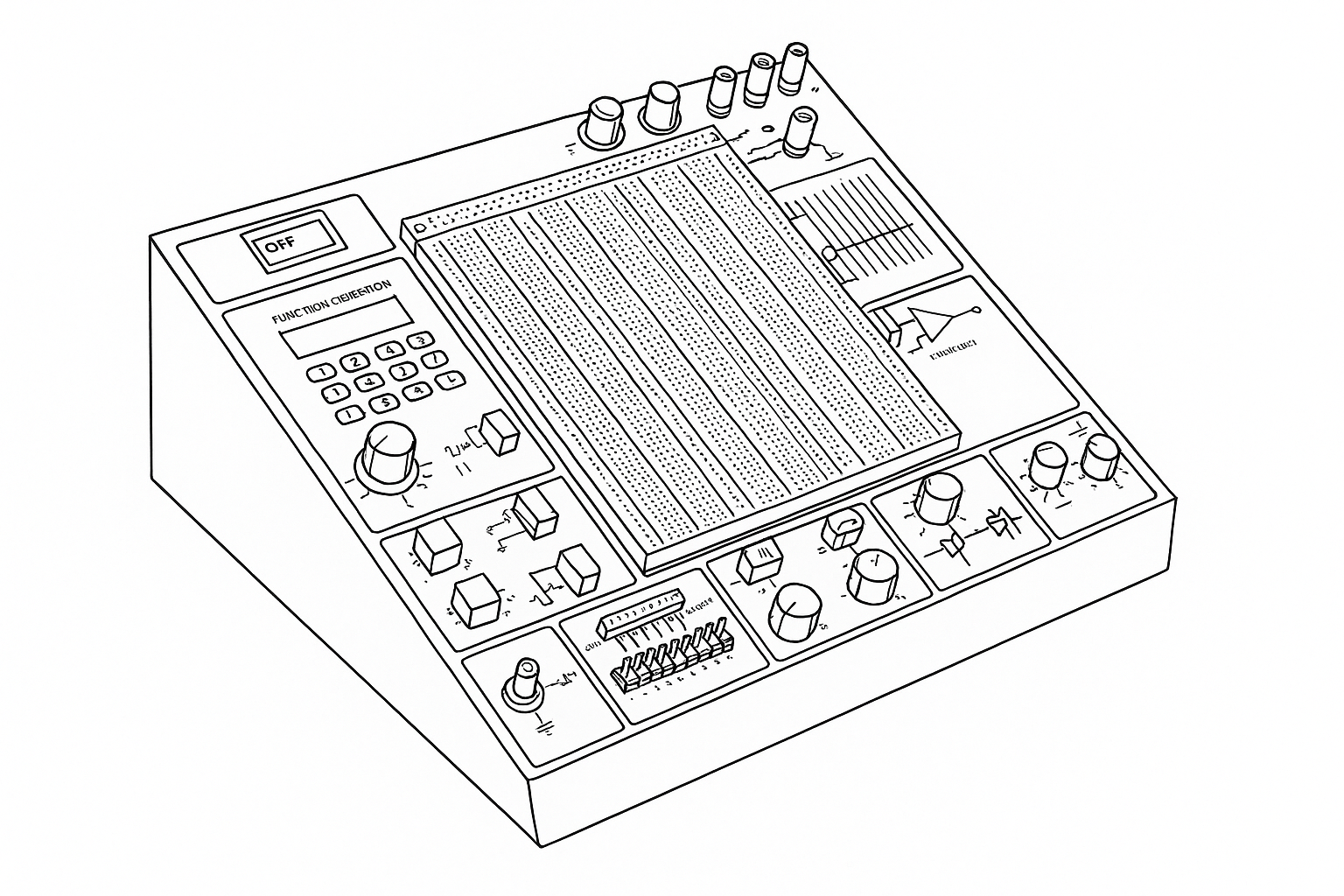
It could look like useful for hobbyist, but it is an expensive, big, uncomfortable device, usually. For professional using it is not an adequate solution, because td does not allow you to see what happens in very short time slots. For example, you need to monitor a 8bit bus behaviour after one millisecond after some digital input signal. In this case, this kind of devices is absolutely unuseful. Unfortunately, many Italian companies still use the same deplorable methodology, today too! Their test plans do not respect the V-model, and their firmware developers have to work on-site only.
But the smarter companies use advanced and complicated devices that allow them to test their electronic products remotely, in deeper and easier way. These tools are very sophisticated and programmable simulator, where they can simulate the external environment in realistic and reliable way. These tools' class is called HILO (Hardware In the LOop).
This project aims to provide a low-cost and very very simple HILO. This one offers less and more limited features, obviously.
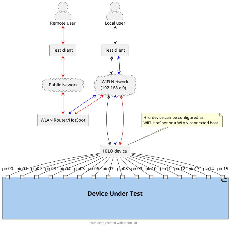
This HILO has two operating modes, that the user can set using the tester client GUI. In the first one (test-mode), the user can monitor the DUT behavior for output-pins activities that run fast or for a short time periods. In the second one the user can change the HILO's output-pins, directly, and verifies the DUT's behavior as consequence.
Test mode: the user has to create a DUT test-recepit where he has to define the HILO's output-pins values, when they change during the test, and the max frequency of the changes. This synchronization will be also used to read the HILO's input-pins. Before to start the test, the HILO will convert the pin-status changes definitions in a scheduled output data sequence. When this raw-data sequence is ready, a bit configuration will be sent to the output-pins on every chock pulse, and the input pins will be read.
Interactive mode: In this mode, the user will be able to change the HILO's output-pins values and check for the input ones status, interactively. It is a good way to get an overview on the DUT's behavior, but, because you cannot schedule the changes with a precise time, it is not adequate for real-time interactions.
In order to get a very fast, relayable, and flexible communication channel between the test-client software and the HILO's interface, TCP/IP limk has been selected. In fact, it allows a huge transfer rate, a very high quality error checking and retransmission, and virtually-infinite distances. It allows the test operator to work remotely respect to the HILO device, and the DUT, bviousely. In order to make the HILO device using as comfotable as possible, WiFI connection has been selected. In this way the test operator can set its own test-desk without to take care of boring cables to connect to it.
This project is a free software; you can redistribute it and/or modify it under the terms of the GNU Lesser General Public License as published by the Free Software Foundation; either version 3.0 of the License, or (at your option) any later version.
For further details please read the full LGPL text file. You should find a copy of the GNU General Public License document in the root folder of the project; if not, write to the
Free Software Foundation, Inc.,
59 Temple Place, Suite 330,
Boston, MA 02111-1307 USA| Qty | Value | Footprint | References |
|---|---|---|---|
| 32 | 10K | Resistor_SMD:R_1206_3216Metric | R105, R106, R107, R108, R109, R110, R111, R116, R119, R122, R124, R127, R130, R132, R133, R134 +16 |
| 16 | 100K | Resistor_SMD:R_1206_3216Metric | R55, R83, R115, R118, R121, R123, R126, R129, R131, R141, R144, R149, R152, R154, R157, R159 |
| 16 | 10nf | Capacitor_THT:C_Disc_D4.3mm_W1.9mm_P5.00mm | C1, C2, C3, C4, C5, C6, C7, C8, C9, C10, C11, C12, C13, C14, C15, C16 |
| 16 | 1K | Resistor_SMD:R_1206_3216Metric | R17, R54, R82, R112, R113, R114, R117, R120, R125, R128, R140, R146, R147, R148, R151, R156 |
| 16 | 5K | Resistor_SMD:R_1206_3216Metric | R1, R2, R3, R4, R5, R6, R7, R8, R9, R10, R11, R12, R13, R14, R15, R16 |
| 16 | BC327 | Package_TO_SOT_THT:TO-92_Inline_Wide | Q25, Q34, Q51, Q52, Q53, Q54, Q55, Q56, Q57, Q58, Q59, Q60, Q61, Q62, Q63, Q64 |
| 16 | BC817 | Package_TO_SOT_SMD:SOT-23 | Q1, Q2, Q3, Q4, Q5, Q6, Q7, Q8, Q9, Q10, Q11, Q12, Q13, Q14, Q15, Q16 |
| 16 | HK19F-DCxxV-SHC | Relay_THT:Relay_DPDT_Finder_30.22 | K1, K2, K3, K4, K5, K6, K7, K8, K9, K10, K11, K12, K13, K14, K15, K16 |
| 8 | MIC4427 | Package_SO:MSOP-8_3x3mm_P0.65mm | U1, U2, U3, U4, U5, U6, U7, U8 |
| 3 | Conn_02x09_Top_Bottom | Connector_PinHeader_2.54mm:PinHeader_2x09_P2.54mm_Vertical | DirControl_1, I/O-LinesToDev_1, I/O-LinesToMicro_1 |
| 1 | Conn_01x02 | Connector_PinHeader_2.54mm:PinHeader_1x02_P2.54mm_Vertical | J1 |


kwiecinski/BMS-and-offgrid-photovoltaic-management-system
Project contains BMS for lead-acid batteries and ESP-based board used to pull information from EASUN offgrid inverter, energy meters and sensors.


rusefi/hw_microRusEfi
microRusEfi board for rusEfi ECU


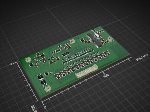

It measures 138.4 × 80.3 mm and has 4 copper layers, 1.6 mm thick.
156 parts, built around the MIC4427ZM, BC327 and BC817. The full list of its parts is on this page, with links to each part's symbol and footprint where PCBKit's library has them.
From the catinella/HILO repository on GitHub, at the commit this page was made from: the board is PCB/IOlinesManagement/main.kicad_pcb and its schematic PCB/ElectricProtections/fuses.kicad_sch. PCBKit opens the board in the browser, with nothing to install.
Its repository states no licence, so its author keeps all rights: ask catinella before reusing the design.